18. Vibration
• Every moving system has some amount of vibration. This is a natural result of unbalanced components, rubbing, reversals, etc.
• Some vibrations are very predictable, and can be estimated mathematically, and their effects compensated for.
• Mathematically a vibration is a displacement/force/velocity/acceleration of small amplitude that will ‘shake’ and object.
18.1 Vibration Modeling
• The most significant vibration in engineered systems is periodic. In these systems there is often an approximate spring-mass-damper system that gives us a second order response to disturbances.
• In vibration modeling we typically assume that all components are linear. In a linear system the forcing (input) frequencies are directly related to response (output) frequencies.
• In non-linear vibration systems we end up with the frequency of the forcing function being transformed to other frequencies. This tends to make the vibrations seem less clear, and appear more chaotic.
• There are a few types of descriptive terms for these systems,
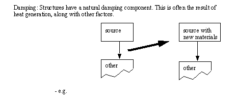
Damping Factor: The damping factor will indicate if vibrations will tend to die off. If the damping factor is too low the vibrations may build continually until failure.
Forced Vibration: When a periodic excitation is applied to these systems they will tend to show a steady state response
Free Vibration: When displaced/disturbed and released there is an oscillation at a natural frequency for any system. This is one measure of a system, and is typically induced by displacing a system and letting it go.
Natural Frequency: Each system will have one or more frequencies that it will prefer to vibrate at. When we excite a system at a natural frequency the system will resonate, and the response will become the greatest.
Response: This is a measure of how a system behaves when it is disturbed. For example, this could be measured by looking at the position of a point on a mechanism.
Steady State Response: After a system settles down it will assume a regular periodic response, this is steady state. The steady state excludes the transient.
Transient Response: When a forcing function on a system changes, there will be a short lived response that tends to be somewhat irregular. The transient will eventually die off, and the system will settle out to a steady state.
• These systems can be modeled a number of ways, but we typically start with a differential equation.
18.1.1 Differential Equations
• In modeling any linear system we are best to start by developing a differential equation for the system components.
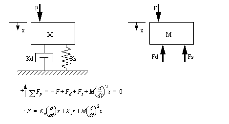
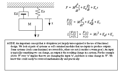
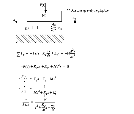
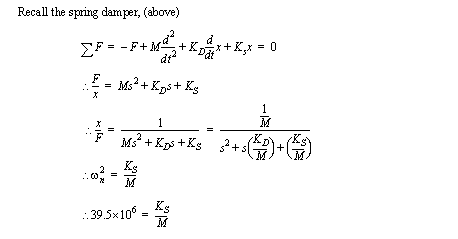
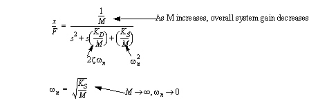
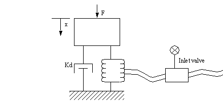
• Consider the simple spring-mass-damper system shown below. A free body diagram can be drawn for the mass ‘M’, and a sum of forces can be written, and expanded with the values for the mechanical components.
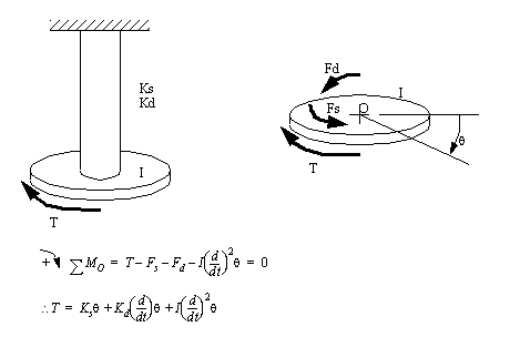
• We may also consider a torsional vibration. We will assume that the vertical shaft has a stiffness of Ks and a damping coefficient of Kd. There is an applied torque ‘T’ and a moment of inertia ‘I’.
18.1.2 Modeling Mechanical Systems with Laplace Transforms
• Before doing any sort of analysis of a vibrating system, a system model must be developed. The obvious traditional approach is with differential equations.
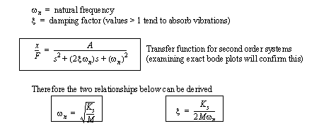
18.1.3 Second Order Systems
• Basically these systems tend to vibrate simply. This vibration will often decay naturally. The contrast is the first order system that tends to move towards new equilibrium points without any sort of resonance or vibration.
• Some basic relations,
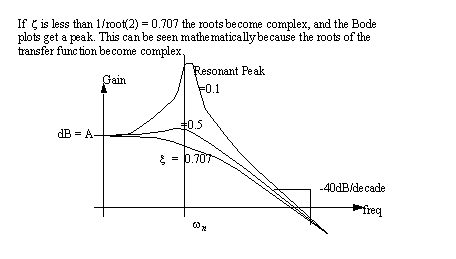
• These generally have an effects on the Bode plot that are very evident.
• Under the influence of damping, the natural frequency will shift slightly,
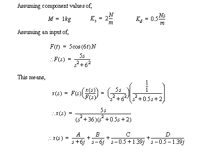
• To continue the example with numerical values
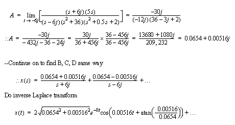
18.1.4 Phase Plane Analysis
• When doing analysis of a system that has both a steady state and transient response it can be handy to do a phase plane analysis to help separate out the components.
• To construct a phase plane graph we plot the value of a response variable against it’s first or second derivative.
• The shape of the graph exposes the phase between the displacement, and one of the derivatives. Here we see the system start to spiral out to an outer radius. The change in the radius of the spiral is the transient, the final radius is the steady state. If the forcing function changed, the path would then shift to a new steady state position.
18.2 Control
• Vibrations are the natural result of many engineered systems.
• These vibrations can become significant when they shake carefully designed structures, or induce sounds in the air.
• As an engineer attempts to suppress or negate vibrations and sound, one of the most powerful weapons is a good analytical understanding of the phenomena.
18.2.1 Vibration Control
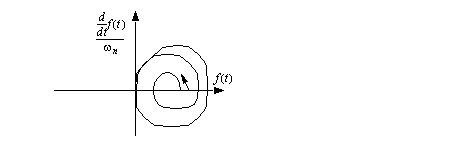
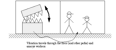
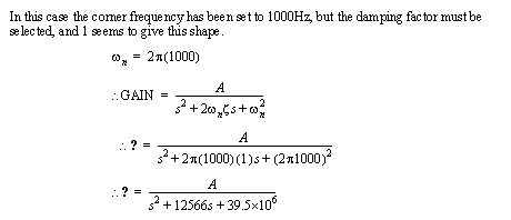
• If this displacement is induced by a machine in the next room, and it travels through the floor, we want to isolate the noise source for the high frequency (2000Hz) that will be noticeable as a whine.
• Your boss asks you to design a mounting for the machine that gets rid of the high frequency whine.
• In this case the bode plot would reduce the noise by over 40dB for the high pitch sound. For the frequencies below 1000 Hz there would not be much reduction, but since this is 1/100th the frequency of the original sound, it should not be a problem.
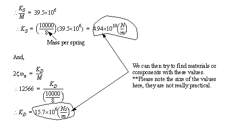
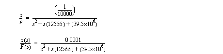
• We check the manuals and find the machine weighs 10000kg, and has 8 mounting points.
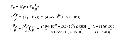
• The result would look something like,
• The force transmitted to the floor is,
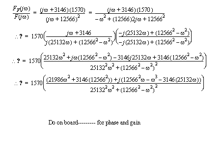
• To find gain,
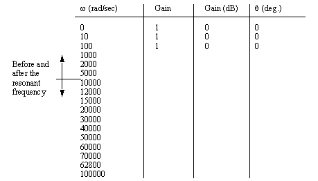
• We can develop a table of gains and phase angles for the isolator
• Consider damping at various frequencies, but consider that with damping the isolation was reduced at the high frequency, but the resonance was also reduced.
18.3 Vibration Control
• types
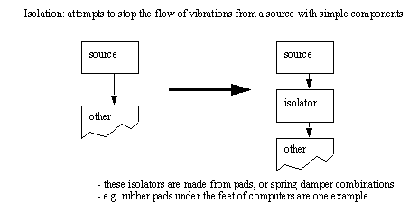
18.3.1 Isolation
• We have already done an example of using springs for damping, but, what are the practical options,
Springs: good for low frequencies because they are not massless as assumed. In fact, they have a damping ration of about 0.005. They are also well suited to harsh (long life) environments. They can have problems with “rocking”.
Elastomeric Mounts: Rubber compounds best used in compression, also good for shear. Common ranges are 30-durometer for soft, low K rubber, to 80-durometer high K rubber (damping ratio about 0.05). These materials are good for high frequencies.
Isolation pads: Cork, felt, fiberglass. Frequencies start at low values (18Hz and up for fiberglass), common damping coefficients for cork and felt are .06.
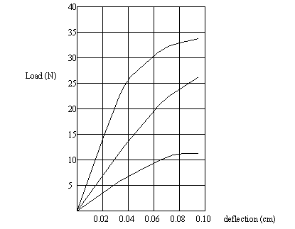
• Elastomers are not linear, so the spring constant will vary as they are loaded. Graphical solutions work well when finding spring constants. Some example curves are given below.
• A solution can be done entirely with graphical methods. Manufacturers will provide graphs for specific materials and thicknesses.
• Note: When designing you should always attempt to get the natural frequency at least three times lower than the frequency to be damped.
• The same type of design techniques can be done with cork. (Note: they would have similar graphs to those for elastomers)
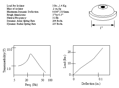
• A set of specifications for an elastomer isolator are summarized below,
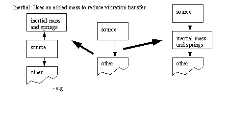
18.3.2 Inertial
Inertial Blocks: Increase the mass of the object to decrease vibration amplitude, and decrease natural frequency.
Absorption: A secondary mass is added to draw off, and hopefully cancel out, vibrations
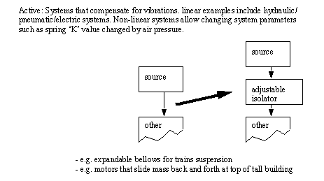
18.3.3 Active
Active Systems: These systems are becoming very popular in new cars, etc. The example below uses a bellows with an adjustable pressure ‘P’. This pressure over area ‘A’ gives a spring constant ‘K’ and height ‘h’. If the pressure in the bellows is adjusted by the addition of gas, the spring constant will rise, tending to damp out different vibration frequencies (remember the ideal gas law ‘PV=nRT’).
• The ‘K’ values vary significantly for Elastomers and Isolation pads as the load varies, therefore graphical values are often required to find the spring constants.
• An example of a practical active vibration control system is piezo electric actuators mounted on the skin of an airplane wing. When unwanted vibrations occurred in the wings the actuators could have voltages applied to counteract the vibrations (both axial and torsional). [Mechanical Engineering, 1995]
18.3.4 References
18.1 Mechanical Engineering, “Controlling Wing Flutter With Miniature Actuators”, Mechanical Engineering Magazine, ASME, 1995.
18.4 Vibration Measurement
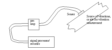
Vibration Source: hammers can be used to generate impulse/step function responses. Load cells/vibrators can be used to excite frequency responses (Bode plots and phase shift plots)
Sensors: Velocity Pickups/Accelerometers: lightweight devices that are mounted on structures. They produce small voltages (approx. 10mV). Velocity meters are not as accurate as accelerometers. Accelerometers are very common, and are used for vibrations above 1KHz. Many other sensors are possible.
Preamplifiers: Can power sensors, filter and amplify output.
Signal Processor: Many types used, from software packages, to older pen based plotters, or tape recorders
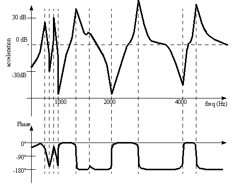
• Consider the example of an amplitude and phase plot measured for a real device,
18.5 Vibration Signals
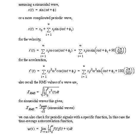
• Some of the wave properties of interest,
• It is worth recalling the discussion of a signal spectrum
18.6 Vibration Transducers
18.6.1 Velocity Pickups
• Output voltage is proportional to velocity (V/(cm/s))
• These devices have low natural frequencies, and are used for signals with higher frequencies.
• well suited to measuring severe vibrations, but it may be affected by noise from AC sources.
• because signals are velocity, some form of integration must be done, making these devices bulky, and somewhat inaccurate
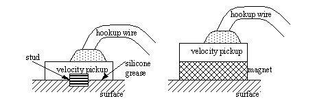
• There are two common methods for mounting velocity pickups,
Magnetic mounts allow fast and easy mounting, but the magnetic mount acts as a slight spring mass isolator, limiting the frequency range.
Stud mounted transducers have a thin layer of silicone grease to improve contact
18.6.2 Accelerometers
• Compared to velocity pickups
smaller
more sensitive
wider frequency range
• electronic integrators can provide velocity and position
• The accelerometer is mounted with electrically isolated studs and washers, so that the sensor may be grounded at the amplifier to reduce electrical noise.
• Cables are fixed to the surface of the object close to the accelerometer, and are fixed to the surface as often as possible to prevent noise from the cable striking the surface.
• Background vibrations in factories are measured by attaching control electrodes to ‘non-vibrating’ surfaces. (The control vibrations should be less than 1/3 of the signal for the error to be less than 12%)
• Piezoelectric accelerometers typically have parameters such as,
-100to250°C operating range
1mV/g to 30V/g
operate well below one forth of the natural frequency
• Accelerometer designs vary, so the manufacturers specifications should be followed during application.
• There is often a trade-off between wide frequency range and device sensitivity (high sensitivity requires greater mass)
• Two type of accelerometers are compression and shear types.
• Mass of the accelerometers should be less than a tenth of the measurement mass.
• Accelerometers can be linear up to 50,000 to 100,000 m/s**2 or up to 1,000,000 m/s**2 for high shock designs.
• Typically used for 10-10,000 Hz, but can be used up to 10KHz
• Temperature variations can reduce the accuracy of the sensors.
• typical parameters are,
• These devices can be calibrated with shakers, for example a 1g shaker will hit a peak velocity of 9.81 m/s**2
18.6.3 Preamplifiers
• The input can be either current or voltage
• sensor signals often have very low values.
• the output of preamplifiers is typically voltage
• these devices can also provide isolation both to and from the sensor
• current amplifiers generally are more costly, but they are more immune to noise.
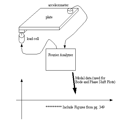
18.6.4 Modal Analysis
• Basically, excite a vibration, and measure how it is transmitted through a structure
18.7 Attenuating Vibrations
• Vibrations are basically the result of cyclic applications of forces. After the vibrations have been identified as frequencies, the phenomenon can be associated with physical design features.
18.7.1 Sources
• unbalanced rotating masses: these can be overcome by addition of counterweights
• rubbing will result in partial or full contact during some repetitive motions. Rubbing often worsens and leads to failure.
• misaligned couplings can lead to displacement or bending forces that induce vibrations.
• loose fittings will knock, rock, rub, etc.
• resonance caused by lack of damping.
• oil whirl and whip: oil films in hole shaft bearings can flow in a sporadic manner, causing the shaft to vibrate, sometimes catastrophically.
18.8 Resources
Library
• There are a number of resources available to the student. In many cases older textbooks will contain valuable information.
Computer
18.9 Problems
Problem 18.1 A machine contains a 60Hz source of vibration that disturbs other machines in the same room. Find the spring coefficient, and natural frequency of an elastomer (with a damping coefficient of .05) that will isolate the vibration source.
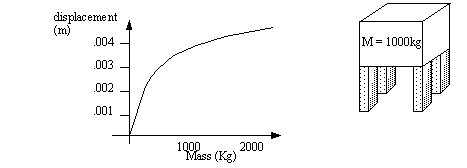
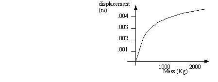
Problem 18.2 There is a large machine that weighs 1000 Kg, and has three legs. We will mount some elastomer under each leg. The graph below shows the characteristics of the isolator. From the graph determine a spring constant (hint: a slope), and determine the natural frequency, and damping ration of the mount.
Problem 18.3 A piece of electronic equipment is to be isolated from a mounting panel which is vibrating at 8Hz. If 90% isolation is specified what static deflection would you expect?
Answer 18.3 0.042 m
Problem 18.4 A piece of mechanical equipment contains a 60Hz electric motor driving a reciprocating mechanism which generates motion excitation at 12Hz. The equipment has a total mass of 450 Kg and is mounted on isolators. To establish some criteria regarding the actual isolation an accelerometer is mounted along the vertical axis of the machine. First, the static deflection is measured and found to be 11mm. When the machine is switched off after operation, the output from the accelerometer is captured as a trace, on a storage oscilloscope. The response ratio between two adjacent positive maxima on the trace (i.e., one cycle separation) is 1.65,
a) find the damped natural frequency of the equipment.
b) determine the percentage isolation (interpolating fig 9.8is adequate if you note your entry figures).
c) if the equipment was operated on a 50Hz supply (motor speed reduced by 17%), explain briefly what changes you would expect in the above results.
Answer 18.4 a) 29.77 rad/s, b) 72%, c) <60%.
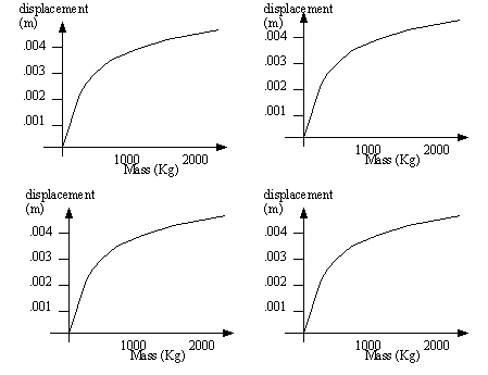
Problem 18.5 It is required to provide 80% isolation for a machine using isolation pads conforming to density C specifications in the figure below (note the damping ratio is 0.05). Mounted equipment will generate dynamic forces at 2600 rpm.
a) What would be the minimum mass of the machine if the total isolator pad area is limited to 750 cm2?
b) for the same pad area and a machine mass of 275 kg, what isolation efficiency would be afforded if density A material were used?
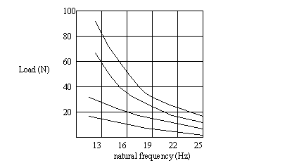
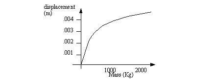
Problem 18.6 Using the data shown in the figure above a total of 4 isolators were selected to isolate a small piece of equipment having a mass of 10kg. The dominant forcing frequency is 60Hz and damping can be neglected.
a) determine the isolation afforded by Isolator B.
b) What would be the result if Isolator C were substituted?
Problem 18.7 Using the figure above, select an isolator to assure 96% isolation efficiency at a forcing frequency of 112Hz (assume no damping). What would be the static deflection of the isolator selected for a load/isolator of 15N
Answer 18.7 0.075cm
Problem 18.8 For a system weight/per isolator of 35N, use the figure above determine what isolation efficiency would be obtained if isolator D were used. System forcing frequency is 80Hz. Damping ratio = 0.
Answer 18.8 95%
Problem 18.9 Cork isolation pads (damping ratio 0.05 use the figure above) are used at the 4 corners of the base of a small machine that weighs 2 KN and generates a forcing frequency of 105Hz. If the pads are 10cm wide by 20cm long, what isolation efficiency would be afforded if they are made of a slab of density C?
Answer 18.9 95%
Problem 18.10 Four springs, each having a spring constant of 2400 N/m are placed at the 4 corners of a centrally loaded baseplate. What is the system weight if the static deflection is 10mm?
Answer 18.10 96N
Problem 18.11 An accelerometer is attached to a piece of equipment and connected via a preamplifier to an oscilloscope. The equipment is mounted on vibration isolators. Assuming a single d.o.f. model which we can see is underdamped, what is the system damping ratio if the measured ratio of the amplitude response at two consecutive positive peaks on the decaying harmonic waveform is 1.8?
Problem 18.12 In the design of an accelerometer the requirement is for the maximum measurement error to be limited to 6% at 1/3 of the resonant frequency (i.e. magnification factor 1.06). What would be the maximum damping ratio to meet these requirements?
Answer 18.12 0.48
Problem 18.13 Using an oscilloscope the ratio of two subsequent maxima was found to be 1.6. Determine the damping ratio.
Answer 18.13 0.075
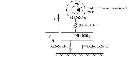
Problem 18.14 A motor (mass M1) and controller (mass M2) are mounted on a heavy base (mass M3). Isolators are used to mount all masses as shown below. Dynamic forces generated by the motor are forcing the system so it will be necessary to determine the forces on M2 and the support structure below M3.
a) show the lumped parameter model which represents the system.
b) using the Force/Current Mobility Analogue show the equivalent electrical circuit.
Problem 18.15 (A long problem) Find the force transmitted by the unbalanced load in the washing machine, to the floor. The rotating mass is 1kg at a distance of 20cm from center, turning at a speed of 30rpm. The assembly consists of the upper drum and motor assembly with mass M2, is rested on a spring, that in turn rests on a large mass. This mass is suspended on a solid floor using a spring/damper combination.
a) Develop the transfer function for the force applied by the eccentric mass to the ground.
b) Determine the input forcing function (from the eccentric mass)
c) Develop the time based reaction using Laplace transforms.
d) Use Fourier transforms to find the effect of the system in steady state.
e) Draw Bode plots for the system.
Problem 18.16 A machine stands on 6 legs in a corner of a room. in total the machine weighs 10,000 kg, and a vibrational force of 50N is applied at 120Hz by a rotating mass, and a force of 2 N is applied at 60Hz by an AC motor. It has been decided that an isolator will be added to reduce the vibration passed to the floor. 6 isolators will be attached to the legs of the machine. The isolators will be spring damper pairs connected in parallel. (Note: assume the floor movement is negligible). The spring constant is 100KN/m, and the damper is 200KNs/m.
a) Draw a Free Body Diagram of the system.
b) Develop a transfer function for the force input to the machine mass, to the force output applied to the floor.
c) Find the isolation for the two vibrations using the results in b).
d) Find a Laplace input function for the vibration, and determine what the Laplace output function will be.
e) Determine the time based response of the function in d).
f) Draw a Bode Plot for the transfer function in b).
g) Use the Bode plot in f) to find the steady state forces applied to the floor.
h) Use the Bode plot in f) to find the isolation of the vibrations.
i) Design an elastomeric isolator (instead of the spring-damper) to get 90% isolation for the 60Hz force.
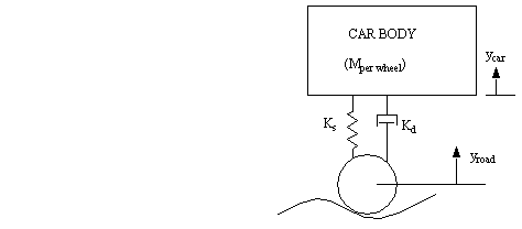
Problem 18.17 Given the car wheel modeled below, relate a change in the height of the wheel to a change in the height of the car. The final result should be a Laplace transfer function of ‘ycar/yroad’.
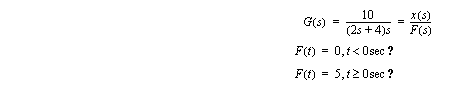
Problem 18.18 Find the time response ‘x(t)’ of a system with a transfer function G(s) that is excited by the force ‘F(t)’.
Problem 18.19 A large machine weighs 1000kg and vibrates at 20Hz, design an inertial damper.
Problem 18.20 A 10kg machine is set on isolation pads and vibrates at 60Hz, what should the natural frequency of an elastomer isolation pad be? If there are 3 pads, what should their spring constant be?
Problem 18.21 A machine stands on 6 legs in a corner of a room. in total the machine weighs 10,000 kg, and a vibrational force of 50N is applied at 120Hz by a rotating mass, and a force of 2 N is applied at 60Hz by an AC motor. It has been decided that an isolator will be added to reduce the vibration passed to the floor. 6 isolators will be attached to the legs of the machine. The isolators will be spring damper pairs connected in parallel. (Note: assume the floor movement is negligible). The spring constant is 100KN/m, and the damper is 200KNs/m.
a) Draw a Free Body Diagram of the system.
b) Develop a transfer function for the force input to the machine mass, to the force output applied to the floor.
c) Find the isolation for the two vibrations using the results in b).
d) Find a Laplace input function for the vibration, and determine what the Laplace output function will be.
e) Determine the time based response of the function in d).
f) Draw a Bode Plot for the transfer function in b).
g) Use the Bode plot in f) to find the steady state forces applied to the floor.
h) Use the Bode plot in f) to find the isolation of the vibrations.
i) Design an elastomeric isolator (instead of the spring-damper) to get 90% isolation for the 60Hz force.
18.10 Sound and Vibration Terms
absorption loss
ambient noise
attenuation
audible range
band pressure level
beats
broad band noise
continuous noise
continuous spectrum
cycle
decibel (dB)
diffuse field
effective sound pressure
free field
frequency
impulse noise
insertion loss
intermittent noise
microbar
microphone
octave
peak-to-peak
peak level
pink noise
pitch
plane sound wave
random noise
reverberation
sound
sound absorption
sound analyzer
sound level
sound level meter
spectrum
spherical wave
standing wave
wavelength
18.11 References
18.2 Irwin, J.D., and Graf, E.R., Industrial Noise and Vibration Control, Prentice Hall Publishers, 1979.