12. Internal Forces in Members
• Up to this point beams have been treated as completely rigid, in truth they are not.
• Even a simple beam with only two forces applied can have a variety of forces and moments internally. These include,
Normal force: This is the tension/compression force along the axis of the member.
Shear force: This is the force acting across the axis of the member.
Bending moment: This moment attempts to bend the beam.
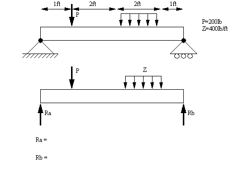
• To start, we need to know the forces and moments acting on the beam, as well as the geometry of the member. The forces on the beam are often found using techniques such as the method of members. In the example below the beam is simply supported.
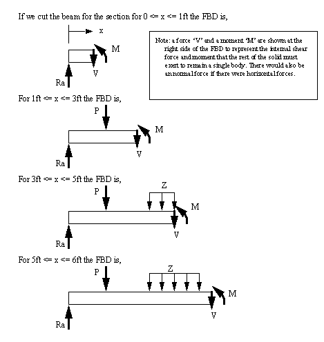
• Internal forces and moments will be found by cutting a beam at the point of interest, and using the internal forces as a reaction to external forces. Note that these can be found at any location in the beam as they vary between pins and other supports.
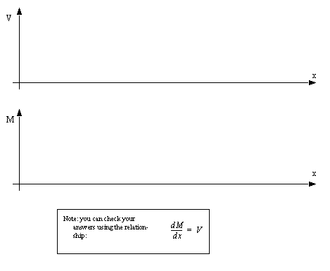
• We can calculate the magnitudes of these forces and draw them on shear force and bending moment diagrams.
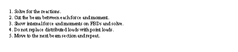
• To review the basic procedure is:
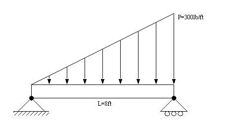
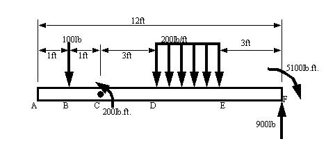
Problem 12.1 Consider the example below. Draw the shear force and bending moment diagrams.
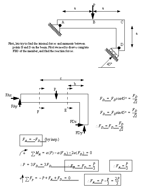
• Consider problem 7.12a) in [Beer and Johnston],
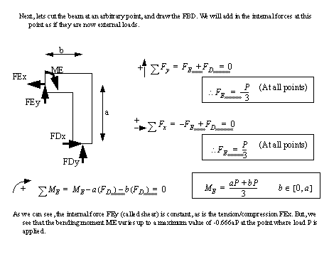
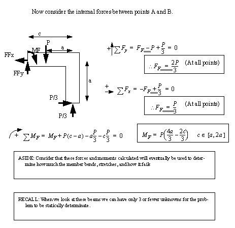
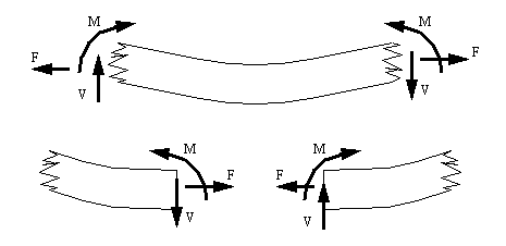
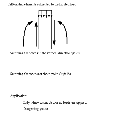
• We can be a little more formal when describing the applied forces. Consider a small part of a beam as shown below. The external shear and bending moments are indicated. Both the shear force V and the bending moment M are drawn in equilibrium. And by convention, both are shown as positive. This is best remembered by looking at the reactions on the left hand side. If we are to draw the internal forces at some point in the beam they would look like those below.
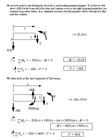
• It can be useful to draw diagrams for both shear and bending moments. These can be done easily by calculating the internal forces for an arbitrary point on the beam.
• As an example lets consider problem 7.38 in [Beer and Johnston]
• NOTE: don’t section at a point load or couple on a beam. At these points the function is undefined. Instead section just before or after.
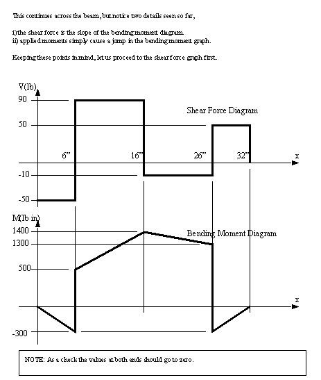
• You may recognize in the last example that the slope of the bending moment diagram was the corresponding value on the shear force diagram.
• Relationships between loads, shear forces and bending moments.
• Consider a simpler technique for developing shear force and bending moment diagrams. First draw the shear force diagram from left to right. The direction of the forces should be added directly to the diagram. Then using the values on the shear force diagram, draw the bending moment diagram.
Problem 12.2 Solve the following example using the relationship between shear and bending moments,
• When considering distributed forces, you can lump the force to find reactions, but you must not lump the forces when drawing the shear force diagrams.
12.1 Problems
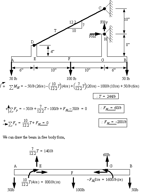
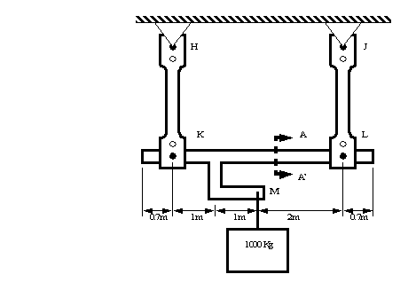
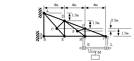
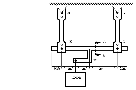
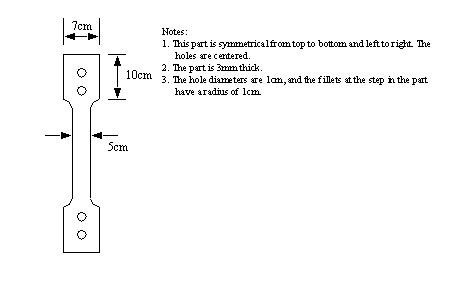
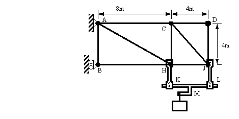
Problem 12.3 a) Find the forces in the tension members HK and JL below.
b) Draw the FBD and then the shear force and bending moment diagrams for the straight section of the beam from K to L.
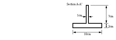
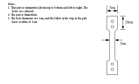
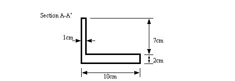
c) Find the centroid and second moment of inertia about the centroid for the beam from K to L. The section is shown below.
d) What is the maximum compressive and tensile stresses and strains in member KL caused by shear and bending? What is the factor of safety for tensile failure if the beam is made from bronze?
e) What is the maximum stress in members HK and JL?
f) Find the tensions and compressions in members EH, DF, DG. Notice that the members analyzed in earlier parts of the problems now apply forces at pins H and J.
Problem 12.4 a) Find the forces in the tension members HK and JL below.
b) Draw the FBD and then the shear force and bending moment diagrams for the straight section of the beam from K to L.
c) Find the centroid and second moment of inertia about the centroid for the beam from K to L. The section is shown below.
d) What is the maximum compressive and tensile stresses and strains in member KL caused by shear and bending? What is the factor of safety for tensile failure if the beam is made from bronze?
e) What is the maximum stress in members LN and MP?
f) Find the tensions and compressions in all members. Notice that the members analyzed in earlier parts of the problems now apply forces at pins H and J.
12.2 References
12.1 Soustas-Little, R.W. and Inman, D.J., Engineering Mechanics Statics, Prentice-Hall, 1997.