5. Moments
• A force is an important type of mechanical effect, but it doesn’t explain bending. For this we use moments.
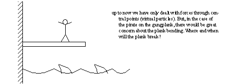
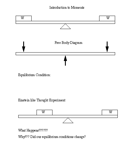
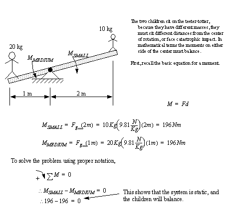
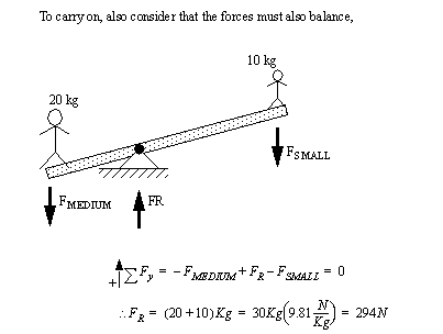
• The classic example is the see-saw,
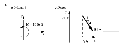
• Considering moments, convert the cases given on the left to those requested on the right.
• Consider the case of a vise. The bottom member must resist the moment caused when the jaws are tightened.
[picture]
• If we look at a normal step ladder we can see that both halves can be analyzed using moments about the top platform.
[picture]
• Certain varieties of tools amplify forces by using moment arms.
[picture]
• We will use the terms moment (M) and torque (T). Numerically the two terms are identical, and are calculated the same way. Typically Moment is used when describing a bending, and Torque is used when describing a twisting moment on a shaft.
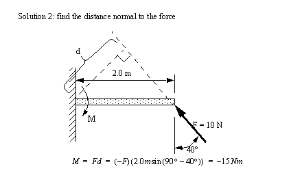
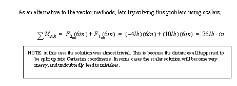
5.1 Calculating Scalar Moments
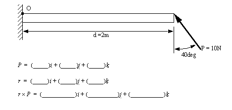
• Next lets consider a case where the forces are not so simple,
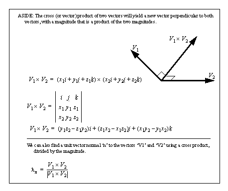
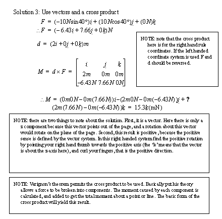
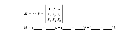
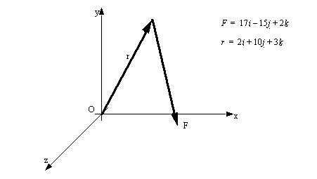
5.2 Calculating Vector Moments
• Consider the problem from before.
• Try completing the following calculation.
• Solve the following planar example.
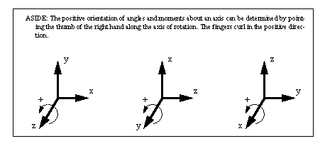
• M is a moment vector that is not in the plane of the paper. Given the value below, find M. Keep in mind the right hand rule must be followed for this calculation to be correct.
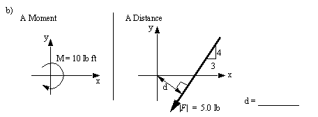
• Considering moments, convert the cases given on the left to those requested on the right.
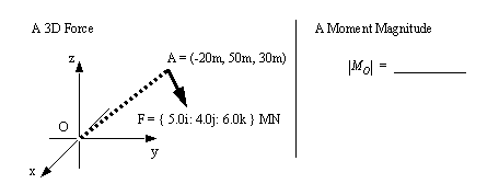
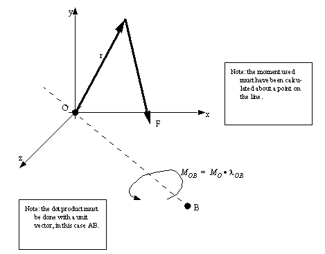
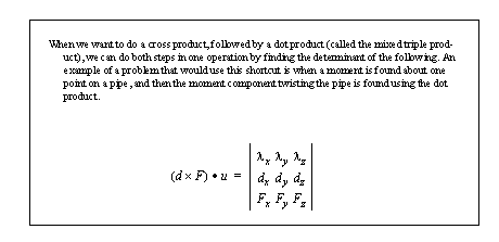
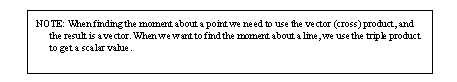
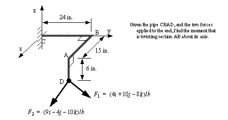
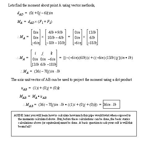
5.3 Moments About an Axis
• Remember: Moment of a force about an axis or point is a measure of the tendency of the forces to rotate the body about the axis or point. Moments are vector quantities and have both magnitude and direction. Since real bodies rotate about axes not points we need to calculate moments about an axis.
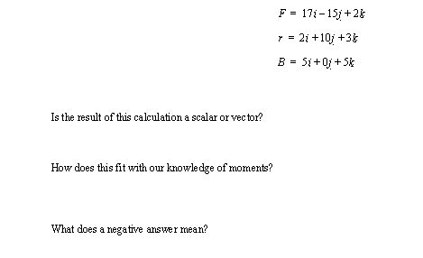
• For the previous figure find the moment about line OB with the following values.
• Consider the bent pipe in the practice problem below, ([Hibbeler, 1992], prob 4-30, pg. )
5.4 Equilibrium of Moments
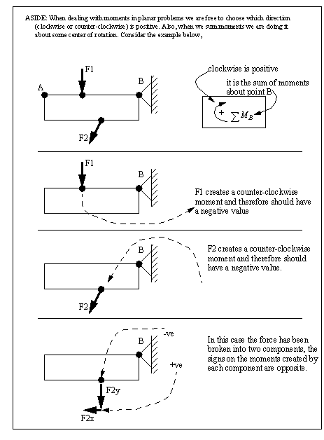
• As with forces, moments also experience equilibrium. If we sum moments ABOUT A SINGLE POINT ON A RIGID BODY, they should total zero for the object the remain static.
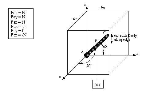
Problem 5.1 The frame below has a ball joint at A, and the other end of the beam at C is smooth and slides freely along the y-axis. A mass of 10kg is added midway along the beam AC. Find the reaction forces at A and C.
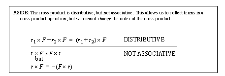
• Another category of problems that may be encountered is to be given a moment vector, and a displacement vector, and be expected to find the applied force. This type of problems is complicated by the fact that the cross product is not reversible, but the solution turns out to be simple.
[picture]
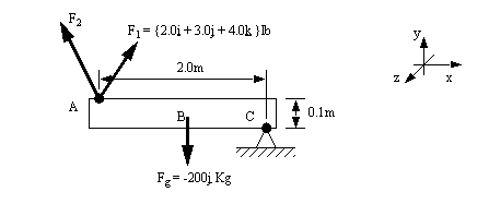
Problem 5.2 Given the two forces F1 and F2 acting on point A and the force of gravity acting on the center of the beam Fg, write the equation for the sum of the moments about C.
5.4.1 References
5.1 Hibbeler, R.C., Engineering Mechanics: Statics and Dynamics, 6th edition, MacMillan Publishing Co., New York, USA, 1992.
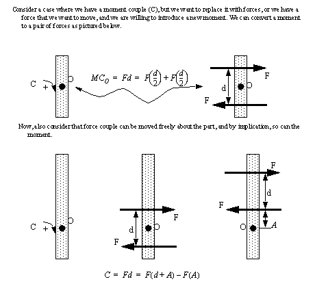
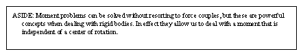
5.5 Using Force Couples to Make Centerless Moments
• Sometimes we are faced with moments that are in awkward positions, We can move these by replacing them with forces and moments in new positions. (Force couples also allow us to rotate the effects of moments)
• Keep in mind that couples cause rotation only, without any translation.
• Consider the basic force couple,
• A force couple acts about an axis. In the previous example the axis was out of the page. The axis can be moved to any position on the rigid body, as long as the direction is maintained. This axis of the couple will be perpendicular to the plane of the forces.
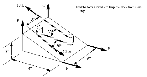
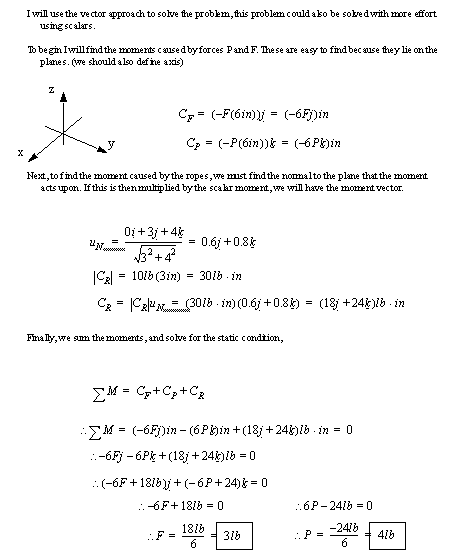
• A sample problem is given using a rope pulling a wedge ([Hibbeler, 1992], prob 4-81, pg. )
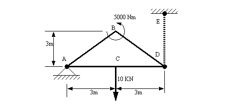
Problem 5.3 Find the tension in the cable DE
Answer 5.3 TDE = 4.17KN
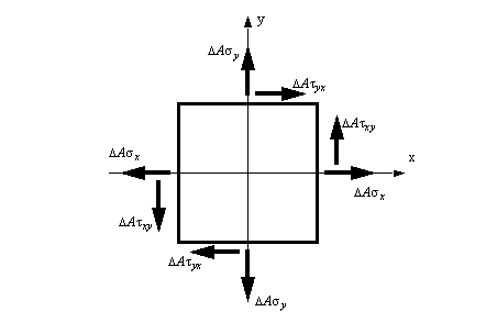
• Consider the stress element that was seen earlier in the stress section
5.5.1 Moving Forces and Equivalent Force Moments
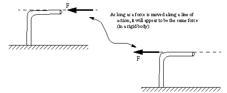
• If a force is moved along the line of action, there are no other modifications needed, (this is called transmissibility)
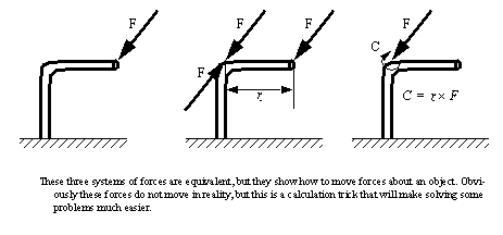
• If a force is not moved along its axis (line of action), then we must create a resultant (make believe) force couple (and it’s resulting moment).
• A sample of a problems that is simplified by moving forces is seen below,
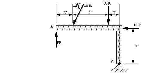
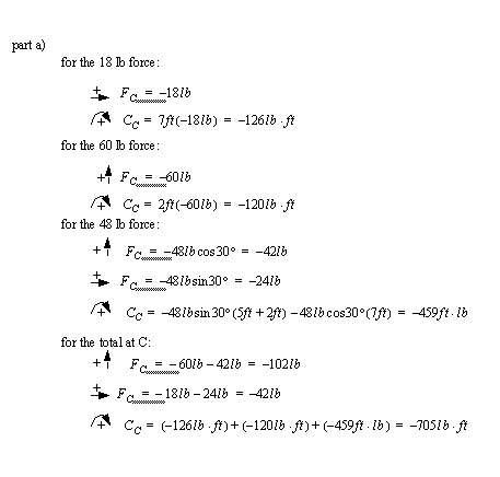
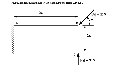
Problem 5.4 Given this beam with applied forces,
a) replace all of the known forces with an equivalent force and moment at C.
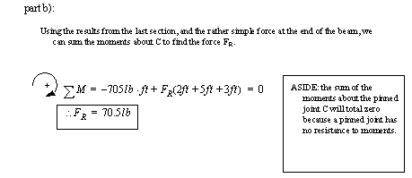
b) find the resulting force FR using the results in a)([Hibbeler, 1992], prob 4-102, pg. )
Answer 5.4
• Try the sample problem below,
Answer 5.4
5.5.2 Problems
Problem 5.5 The pole OA is 5m long and is held firm at base O. It is pulled by two cables AC and AB that each have 1KN of tension. Find the magnitude of the moment at O caused by the two cables.
Problem 5.6 A 500 lb cylindrical tank, 8ft in diameter, is to be raised over a 2ft obstruction. A cable is wrapped around the tank and pulled horizontally as shown. Knowing the corner of the obstruction at A is rough so that the cylinder slips at C but not at A, find the required tension in the cable.
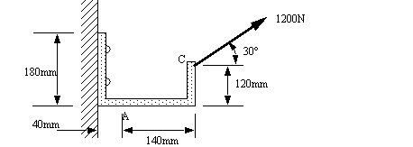
Problem 5.7 A force of 1200N acts on a bracket as shown. Determine the moment Ma of the force about A.
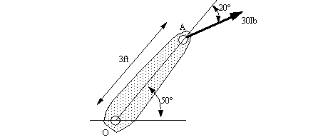
Problem 5.8 A 30lb force acts on the end of the 3ft lever as shown. Determine the moment of the force about O.
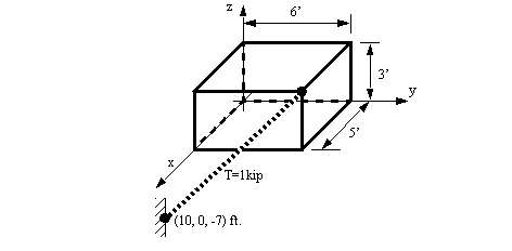
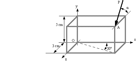
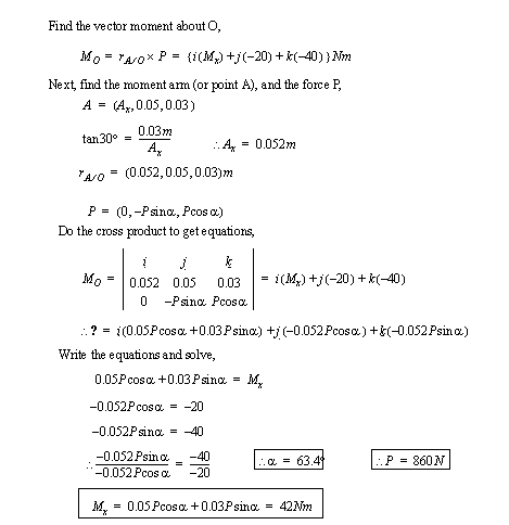
Problem 5.9 A box is shown in the figure below. Find the moment that the tension cable causes about the origin using a cross product. Give the results using components and a magnitude.
Answer 5.9
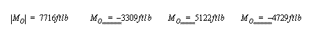
Problem 5.10 A force P acts on a corner of a frame (at A) and creates a moment about the origin (O). We know that the force P is in the y-z plane, the moment about the y-axis is -20Nm, and the moment about the z axis is -40 Nm. Find the magnitude of the moment about the x-axis.
Answer 5.10
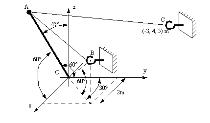
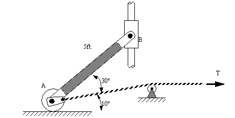
Problem 5.11 The rod has a mass of 20lb., and the mass of joints A & B are both 5 lb. What is the tension ‘T’ in the rope?
Answer 5.11 18.2lb
5.5.3 References
5.2 Beer, F.P., Johnson, E.R., Statics & Mechanics of Materials, McGraw-Hill, 1992.
5.3 Hibbeler, R.C., Engineering Mechanics: Statics and Dynamics, 6th edition, MacMillan Publishing Co., New York, USA, 1992.
5.4 Soustas-Little, R.W. and Inman, D.J., Engineering Mechanics Statics, Prentice-Hall, 1997.


![[picture]](media/egr20900.jpg)
![[picture]](media/egr20903.jpg)
![[picture]](media/egr20907.jpg)
![[picture]](media/egr20922.jpg)