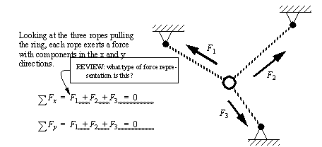
2. Forces
• WHAT?: We look at mechanical structures, and determine the distribution of forces and moments.
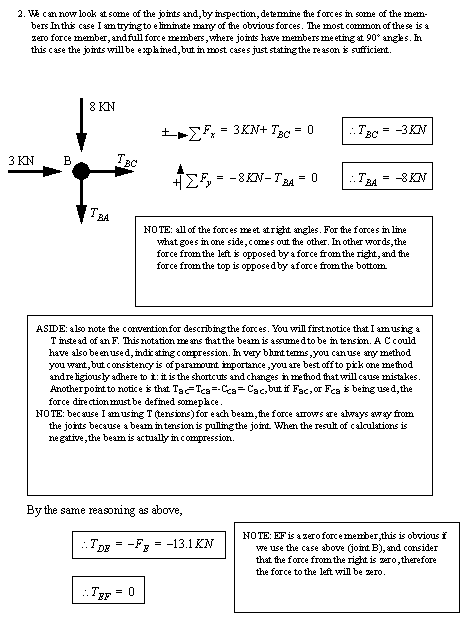
• WHY?: a fundamental subject for every form of Mechanical Engineering (and every other branch of engineering that has ever existed)
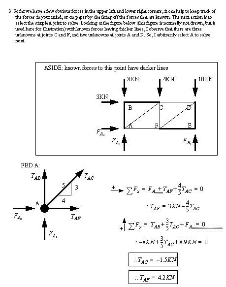
egr20935.jpg
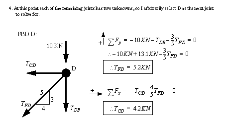
• The difference between statics and dynamics, in brief,
Statics: does nothing, just sits there
Dynamics: moving things
EX1.WM
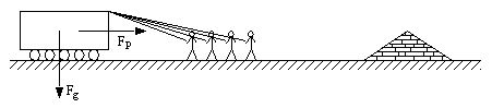
• Consider some of the applications of statics design techniques,
egr20921.jpg
egr20932.jpg
egr20926.jpg
2.1 Some Basic Concepts
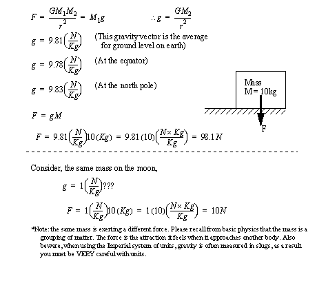
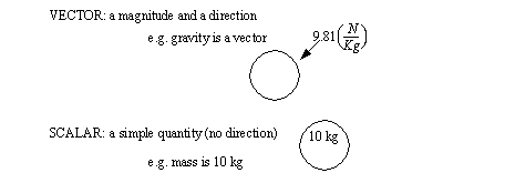
• Mass and force: A mass can exert forces through gravity and other effects. Forces can also be exerted by other phenomenon, such as magnetism.
• We can emphasize the relationship between mass as an absolute and gravity as a local. The effects of gravity are dealt with as forces in most statics problems.
• Force has magnitude and direction. Therefore it is well suited to vectors.
• many forces can also operate on the same object, we can replace these with equivalent forces, called resultants.
• We have both action and reaction forces as well. As we apply action forces, there are forces that will resist, these are called reaction forces.
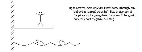
• Some approximations,
we are pretending the forces are applied at points, but in reality a force must be distributed,
we generally assume there are no deflections. This is known as the RIGID BODY assumption.
we often use particle approximations that assume bodies have no size. This simplifies calculations significantly.
Transmissibility: a force can be moved along a line of action.
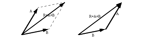
Parallelogram law: a method for adding two forces to get a resultant vector.
2.2 Vector and Scalar Forces
• definitions,
• Recall that vectors can be added or subtracted using the parallelogram law. This is a variation or the triangle law. In both cases we are putting vectors head to tail. These methods favor drafting solutions to problems that are not really necessary with calculators, but they are still very useful for understanding.
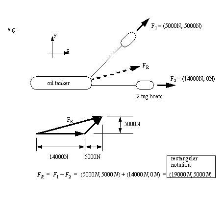
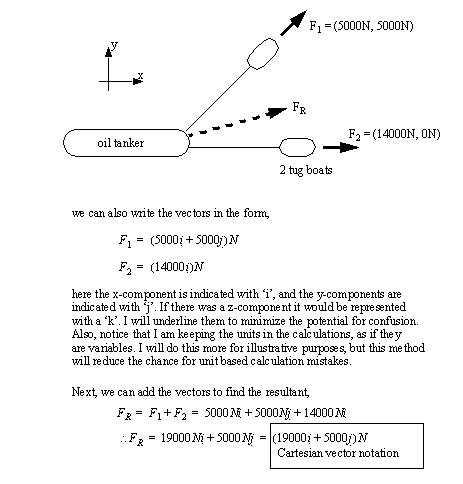
• vectors can be added to get resultant forces in vector (rectangular component) form.
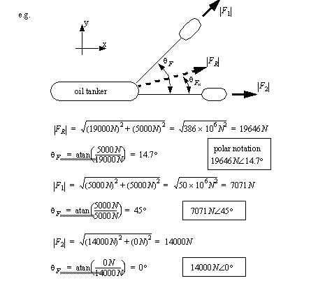
• We can also represent the same forces as scalar magnitudes, and direction,
• we could have also solved this problem using trigonometry.
2.2.1 Cartesian Vector Notation
• Remember from before,
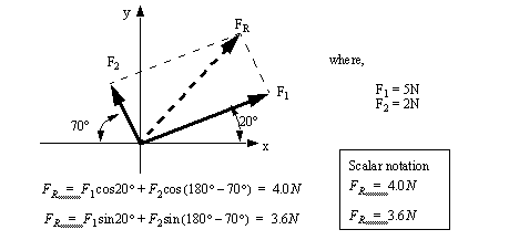
2.2.2 Scalar Notation
• It can also be useful to keep the forces in scalar values, but the direction should still be defined on paper, instead of by convention, as is done with vectors. The most common method is to use x-y-z components, or forces relative to a given direction.
• For example,
• Scalar notation is often made obvious by using ‘x’, and ‘y’, or similar subscripts.
• direction, location, signs, etc. are all defined by convention, and very compact mathematical methods can be used.
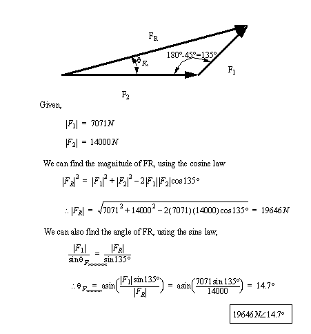
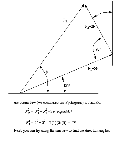
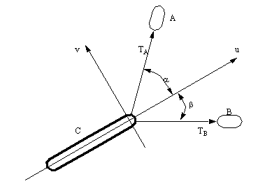
• These problems can also be solved using cosine and sine law force additions on force triangles. Considering the last example,
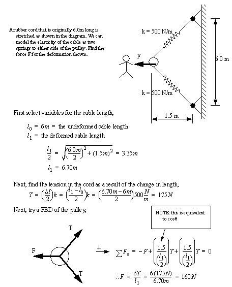
• Consider the large pendulum below as an example where a force tringle could be used to find the tensions in the cables.
egr20928.jpg
egr20927.jpg
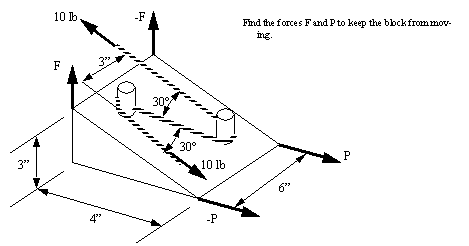
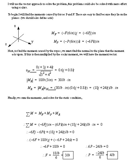
Problem 2.1 Find an equation that relates all of the tensions and angles.
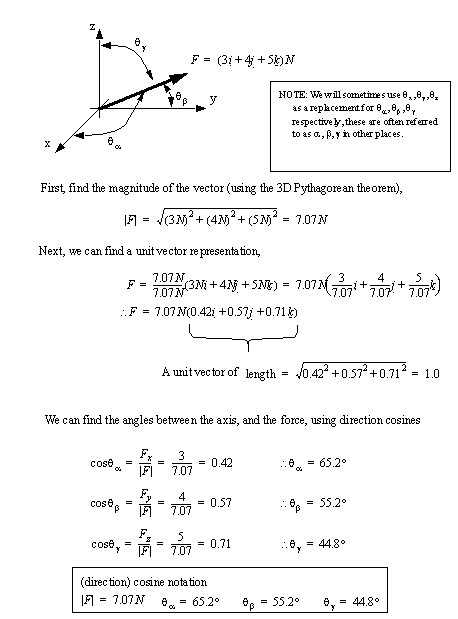
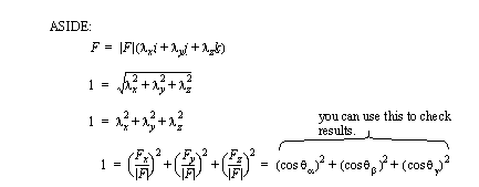
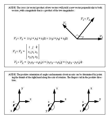
2.2.3 3D Vectors
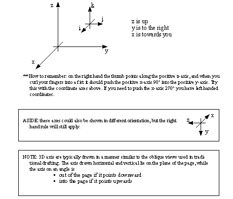
• We will use right-handed coordinates
• Consider the following conditions,
• To emphasize the main relations,
• An example to illustrate this technique is,
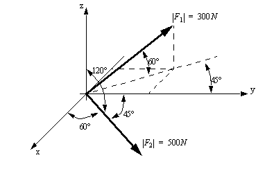
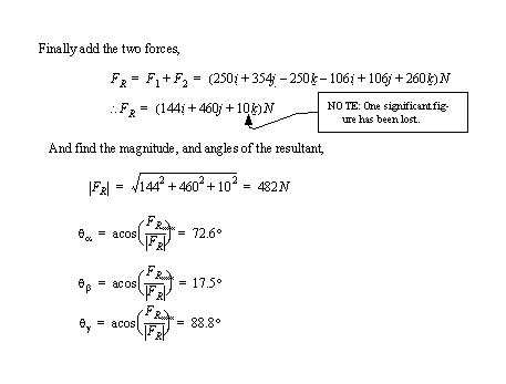
Problem 2.2 ([Hibbeler, 1992], prob. 2-56, pg. 49) Find the resultant force for the two forces shown in vector projection (F1) and cosine notation (F2).
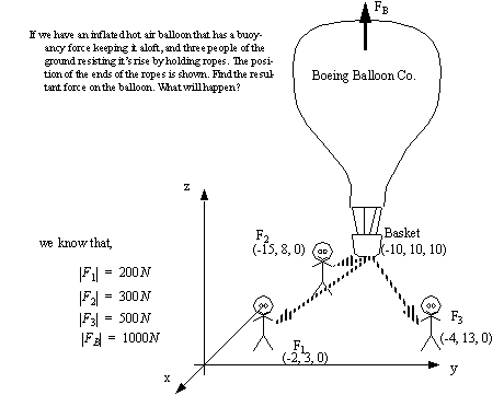
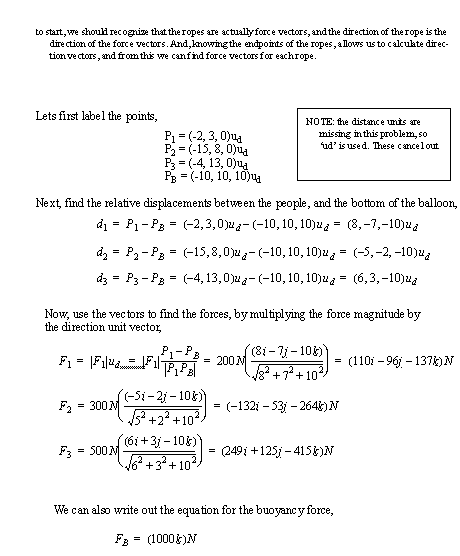
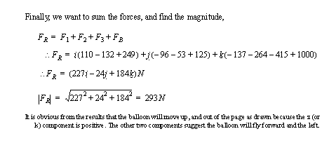
• Consider the case below, where we know positions, and forces, but we want to find the resultant force,
• As a practical example of where 3D vectors might be required, consider the power line pole. It uses a tension cable anchored in the ground to resist the forces exerted by the power lines.
egr20933.jpg
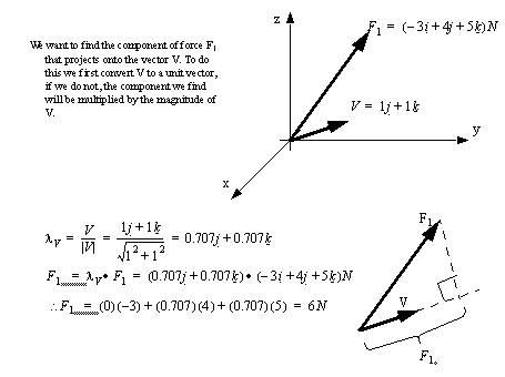
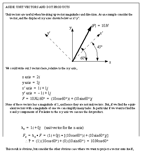
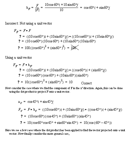
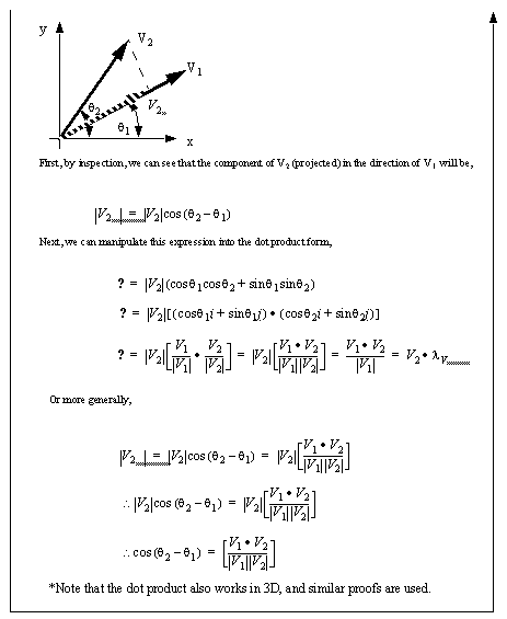
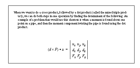
2.2.4 Dot (Scalar) Product
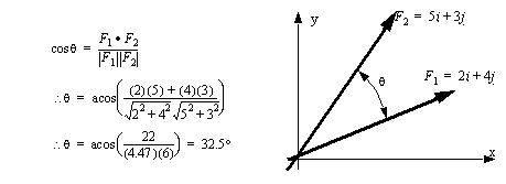
• We can use a dot product to find the angle between two vectors
• We can use a dot product to project one vector onto another vector.
• The use for the dot product will become obvious in later sections.
2.2.5 Summary
• the basics of statics as a topic were covered
• engineering units and calculations
• representations covered in this section were,
scalar values
vector values
rectangular
polar
cartesian
direction cosines
vector projection
direction vectors
• The dot product was shown as a way to project one vector onto another, or final angles between them.
2.2.6 Problems
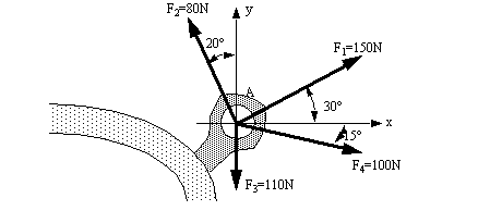
Problem 2.3 Four forces act on bolt A as shown. Determine the resultant of the forces on the bolt.
Answer 2.3 Fx=199N, Fy=14N
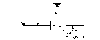
Problem 2.4 Find the tension in cable A and B if the tension in cable C is 100N.
Answer 2.4 TA=71N,TB=71N
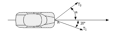
Problem 2.5 A disabled automobile is pulled by two ropes as shown below. If the resultant of the two forces must be 300lb, parallel to the forward roll of the car, find (a) the tension in each of the ropes, knowing that α = 30°, (b) the value of α such that the tension in rope 2 is minimum.
Answer 2.5 a) TA=, b) 70°
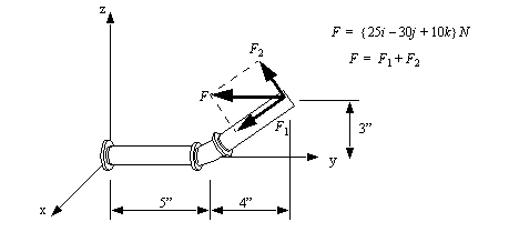
Problem 2.6 A force F acts at the end of a pipe. Determine the magnitudes of the components that act perpendicular to, and along the axis of the end of the pipe. (the pipe lies in the y-z plane)
Answer 2.6 18N along, 36.1N across
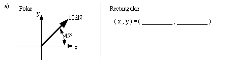
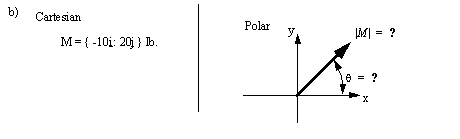
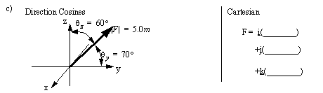
Problem 2.7 Convert between the representations given on the left, and the results requested on the right.
Answer 2.7 a) 7.1dN,7.1dN, b) 22.3lb, 243°, c) 4.0m,1.7m,2.5m
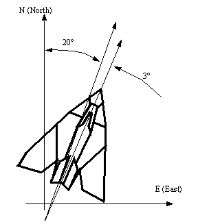
Problem 2.8 An F-117A stealth fighter is supposed top be flying N20°E, but a strong wind from West to East is pushing it off course. If the plane is pointed N20°E, but is actually moving N23°E, and its 22,000 lb engine is at full thrust, a) what force is the wind exerting on the plane? b) What is the answer in newtons?
Answer 2.8 a) Fw= 1137lb, b) Fw= 5070N
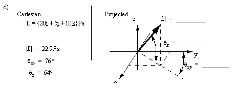
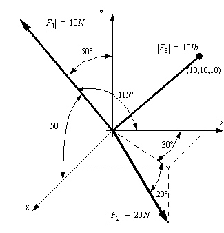
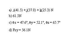
Problem 2.9 Given the system of vectors pictured, a) give the resultant force using Cartesian notation b) find the magnitude of the resultant force in metric units. c) Then then using cosine angles, and finally d) projected onto the x-y plane.
Answer 2.9
2.2.7 References
2.1 Hibbeler, R.C., Engineering Mechanics: Statics and Dynamics, 6th edition, MacMillan Publishing Co., New York, USA, 1992.
2.3 Equilibrium
• Put simply equilibrium describes the condition where all forces are balanced (no acceleration). Static equilibrium describes the state where all forces are balanced, and the object is not accelerating.
• For an object to be in equilibrium, all the forces and moments must be balanced for,
each particle in a rigid body
each rigid body
each object made up of rigid bodies
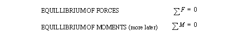
• The basic equations of statics are
• There are two basic balances that must exist in any statics problems.
• if the sum of the forces is not zero, then the system will undergo translation, and the problem cannot be solved with statics methods.
• if the sum of moments is not zero, then the system will undergo rotation, and the problem cannot be solved with statics methods.
• At least one of these two equations will appear in every statics problem.
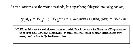
• A simple example,
• Let’s consider a force balance problem, ([Hibbeler, 1992]prob 3-40, pg. )
2.3.1 Problems
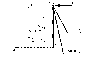
Problem 2.10 Two cables (AB and AC) and a force (P) act on the top of a flag pole (AD). Find the magnitude of force P required to keep the flag pole standing? Assume that cable AB is under 5 KN of tension.
Answer 2.10
2.3.2 References
2.2 Hibbeler, R.C., Engineering Mechanics: Statics and Dynamics, 6th edition, MacMillan Publishing Co., New York, USA, 1992.
2.4 Free Body Diagrams (FBDs)
• Up to this point we assumed very simple forces acting on very small particles.
• In reality mechanical systems have many parts, and we draw an FBD for each part.
• We should divide forces on free body diagrams into two categories,
Internal: these forces act only within a free body, and cancel out, unless we are looking at a section of a free body.
External: these forces act on a free body, and they induce reaction forces. Examples are gravity, and other free bodies.
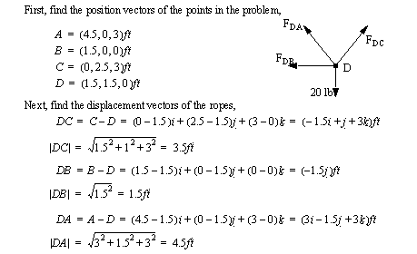
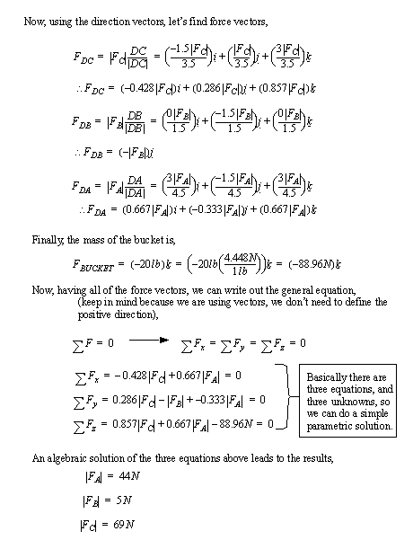
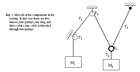
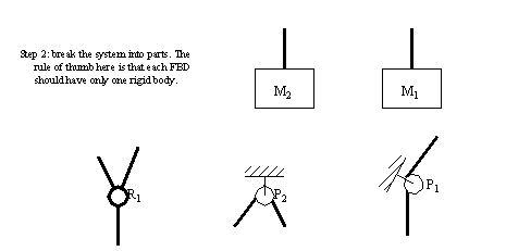
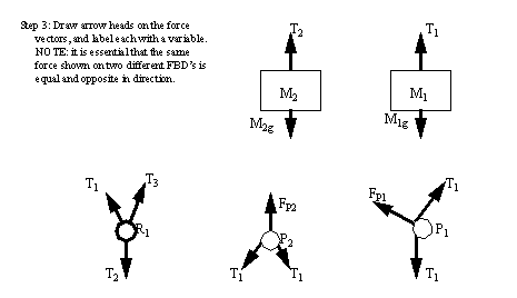
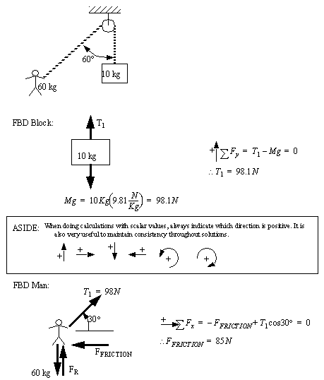
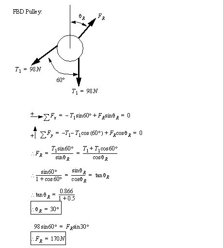
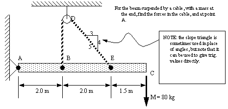
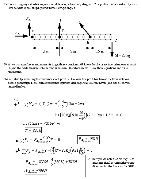
• An example of using free body diagrams for a system is given below with a system of masses, ropes, pulleys and anchors.
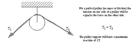
2.4.1 Pulleys and Springs
• Pulleys are basically a wheeled roller that a rope can roll over freely,
• A simple example of a pulley used for lifting a mass is given below,
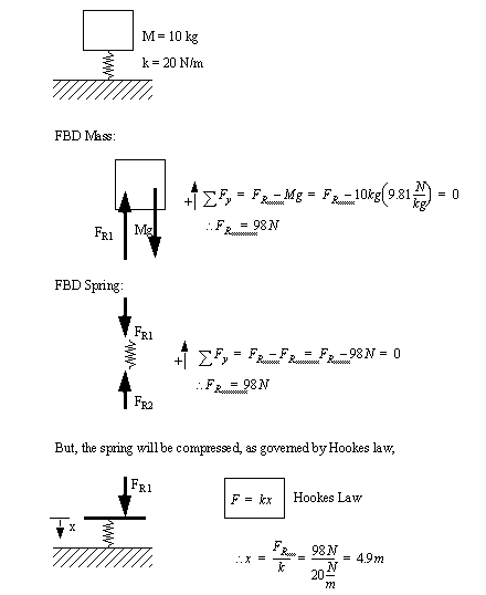
• Springs are a very important engineering tool,
• A sample problem that uses springs is given below, ([Hibbeler, 1992] prob 3-16, pg. )
2.4.2 Summary
• equilibrium of forces and moments
• free body diagrams (FBD’s)
pulleys
springs
anchors
cables
masses
rings
2.4.3 Problems
Problem 2.11 Determine the reactions at B, C and D.
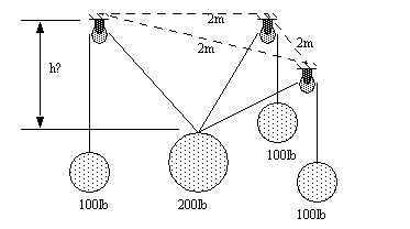
Problem 2.12 Four masses are suspended by cables that are supported by pulleys. The frictionless pulleys are mounted on a flat ceiling. Each of the pulleys is a distance of 2m from the others. Determine the height of the center mass.
Answer 2.12 1.03m
Problem 2.13 The rod has a mass of 20lb., and the mass of joints A & B are both 5 lb. What is the tension ‘T’ in the rope?
Answer 2.13 18.2lb
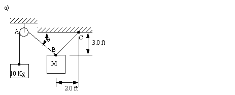
Problem 2.14 For the mass pulley system on the left, a) draw the force triangle on the right, with all angles and magnitudes indicated, then b) find the mass.
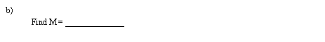
Problem 2.15 Given the three masses below, connected by a cable through three pulleys, determine the final resting height (h2) for the center mass. Assume the pulleys are very small.
Answer 2.15 h2= 2.4m
2.4.4 References
2.3 Hibbeler, R.C., Engineering Mechanics: Statics and Dynamics, 6th edition, MacMillan Publishing Co., New York, USA, 1992.
2.5 Moments
• a force is an important type of mechanical effect, but it doesn’t explain bending. For this we use moments.
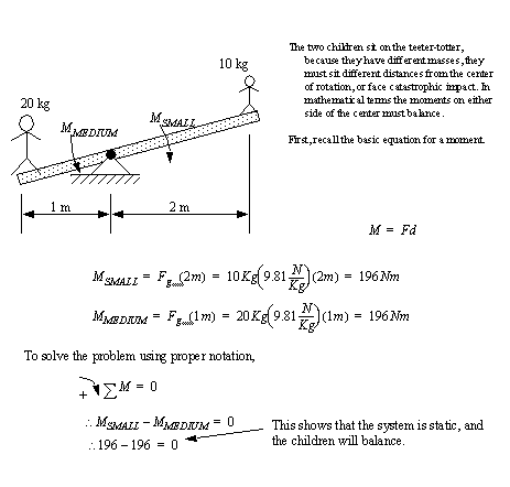
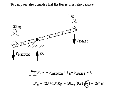
• The classic example is the see-saw,
• Consider the case of a vise. The bottom member must resist the moment caused when the jaws are tightened.
egr20900.jpg
• If we look at a normal step ladder we can see that both halves can be analyzed using moments about the top platform.
egr20903.jpg
• Certain varieties of tools amplify forces by using moment arms.
egr20907.jpg
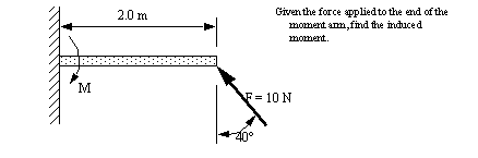
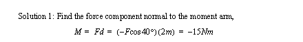
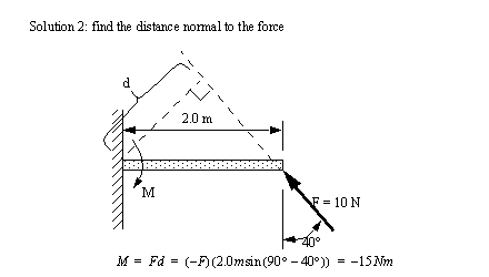
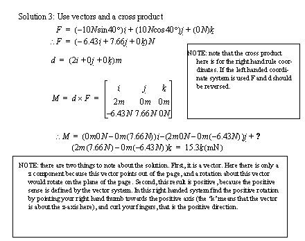
2.6 Calculating Scalar and Vector Moments
• Next lets consider a case where the forces are not so simple,
• Each of these three methods will be required at some time or another, each should be considered fundamental, any that is not learned will make certain problems difficult/impossible to solve.
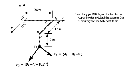
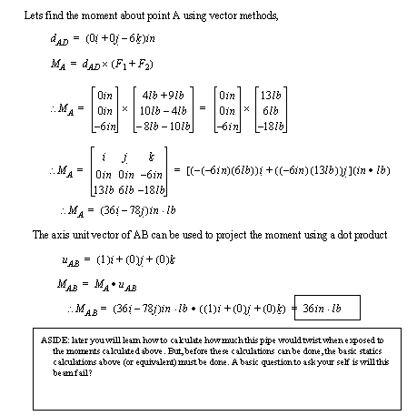
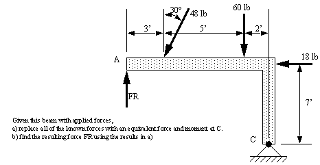
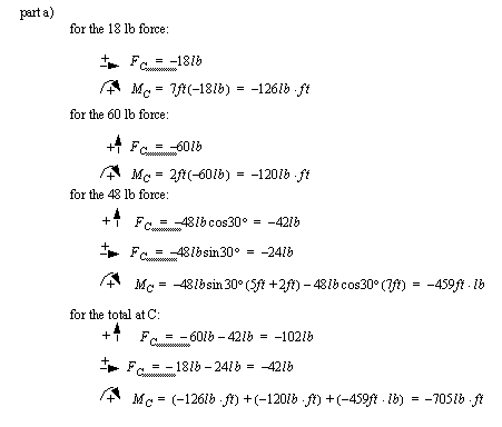
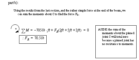
• Consider the bent pipe in the practice problem below, ([Hibbeler, 1992], prob 4-30, pg. )
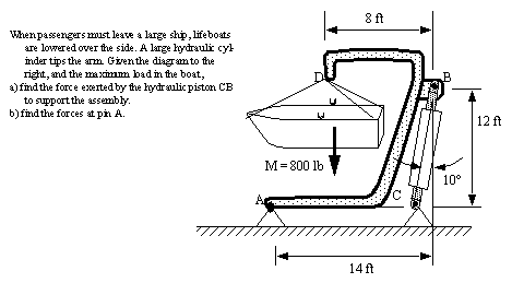
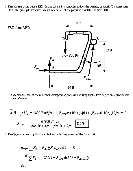
• Finally consider an application of moment calculations as seen below. Here we would need to balance the maximum load allowed against the hydralic cylinders acting on the lifter. This can be done using a sum of moments.
egr20922.jpg
2.6.1 References
2.4 Hibbeler, R.C., Engineering Mechanics: Statics and Dynamics, 6th edition, MacMillan Publishing Co., New York, USA, 1992.
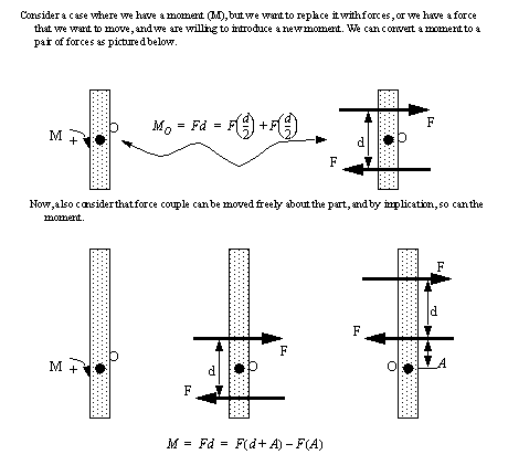
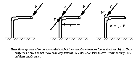
2.7 Using Force Couples to Create Centerless Moments
• Sometimes we are faced with moments that are in awkward positions, We can move these by replacing them with forces and moments in new positions. (Force couples also allow us to rotate the effects of moments)
• Keep in mind that couples cause rotation only, without any translation.
• Consider the basic force couple,
• A force couple acts about an axis. In the previous example the axis was out of the page. The axis can be moved to any position on the rigid body, as long as the direction is maintained. This axis of the couple will be perpendicular to the plane of the forces.
• A sample problem is given using a rope pulling a wedge ([Hibbeler, 1992], prob 4-81, pg. )
2.7.1 Moving Forces and Equivalent Force Moments
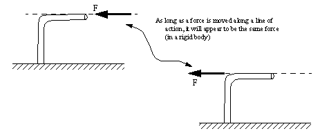
• If a force is moved along the line of action, there are no other modifications needed, (this is called transmissibility)
• If a force is not moved along its axis (line of action), then we must create a resultant (make believe) force couple (and it’s resulting moment).
• A sample of a problems that is simplified by moving forces is seen below, ([Hibbeler, 1992], prob 4-102, pg. )
2.7.2 Problems
Problem 2.16 The pole OA is 5m long and is held firm at base O. It is pulled by two cables AC and AB that each have 1KN of tension. Find the magnitude of the moment at O caused by the two cables.
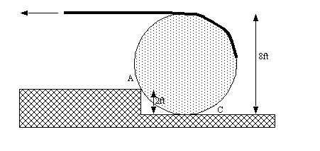
Problem 2.17 A 500 lb cylindrical tank, 8ft in diameter, is to be raised over a 2ft obstruction. A cable is wrapped around the tank and pulled horizontally as shown. Knowing the corner of the obstruction at A is rough so that the cylinder slips at C but not at A, find the required tension in the cable.
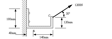
Problem 2.18 A force of 1200N acts on a bracket as shown. Determine the moment Ma of the force about A.
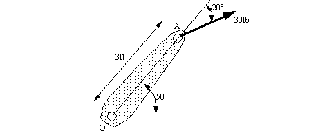
Problem 2.19 A 30lb force acts on the end of the 3ft lever as shown. Determine the moment of the force about O.
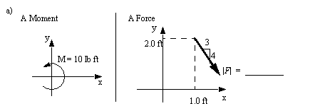
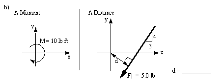
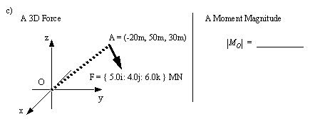
Problem 2.20 Considering moments, convert the cases given on the left to those requested on the right.
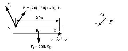
Problem 2.21 Given the two forces F1 and F2 acting on point A and the force of gravity acting on the center of the beam Fg, write the equation for the sum of the moments about C
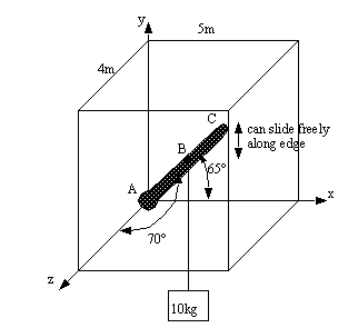
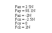
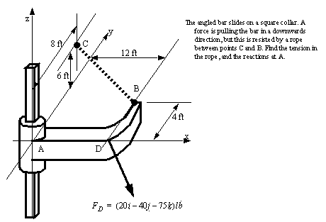
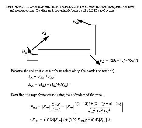
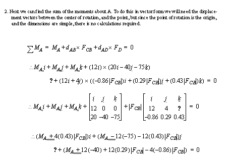
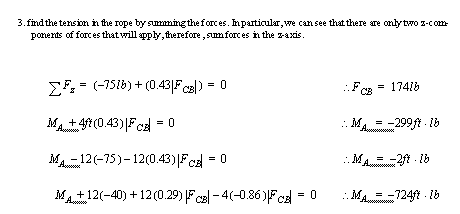
Problem 2.22 The frame below has a ball joint at A, and the other end of the beam at C is smooth and slides freely along the y-axis. A mass of 10kg is added midway along the beam AC. Find the reaction forces at A and C.
Answer 2.22
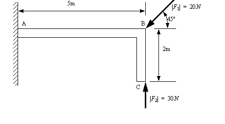
Problem 2.23 Find the moment at A given the two forces at B and C.
Answer 2.23
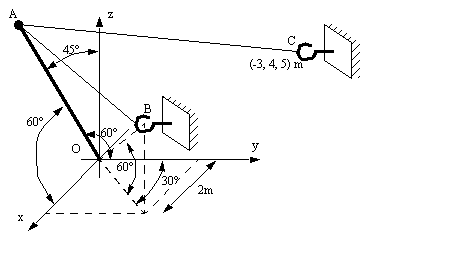
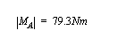
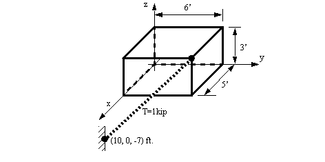
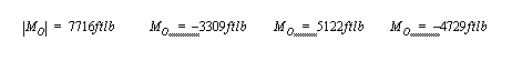
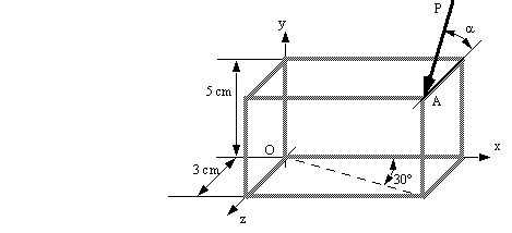
Problem 2.24 A box is shown in the figure below. Find the moment that the tension cable causes about the origin using a cross product. Give the results using components and a magnitude.
Answer 2.24
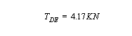
Problem 2.25 Find the tension in the cable DE.
Answer 2.25
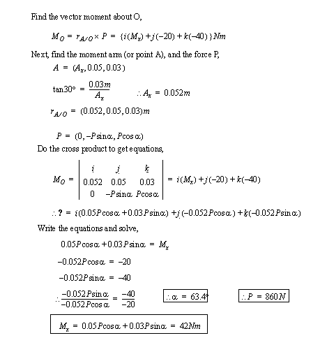
Problem 2.26 A force P acts on a corner of a frame (at A) and creates a moment about the origin (O). We know that the force P is in the y-z plane, the moment about the y-axis is -20Nm, and the moment about the z axis is -40 Nm. Find the magnitude of the moment about the x-axis.
Answer 2.26
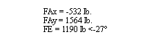
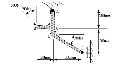
Problem 2.27 Given the force at C and couple at B, find the magnitude and direction of the reaction forces at the supports A and E below.
Answer 2.27
2.7.3 References
2.5 Beer, F.P., Johnson, E.R., Statics & Mechanics of Materials, McGraw-Hill, 1992.
2.6 Hibbeler, R.C., Engineering Mechanics: Statics and Dynamics, 6th edition, MacMillan Publishing Co., New York, USA, 1992.
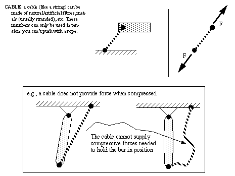
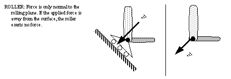
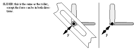
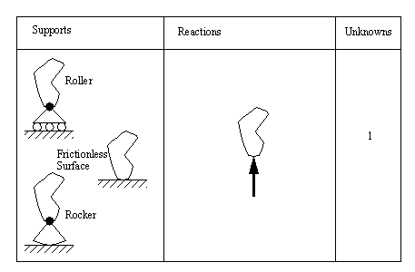
2.8 Reactions and supports
• These symbols are very important to engineers. Their equivalent is the symbols for resistors, transistors, etc in electrical engineering. They are a way to talk about systems in general terms before investing time and resources designing and building the system.
• A subset of these symbols are,
• Other joints include
spring
rod on a smooth surface
rod on a rough surface
pin supports
beams cemented into walls (fixed support)
ball (3D)
ball socket
universal joint
hinge
collar and shaft
2.9 Equilibrium of Forces and Moments
• It is often necessary to solve problems using both sums of moments and forces. Indeed, both of these sums must be equal to zero for the body to be static.
• An example of a problem that has both forces and moments is given below, ([Hibbeler, 1992], prob 5-4, pg. )
stat0000.wm
• Consider the pictures of both the hoists below, they are much like the examples that follow. The red dampers apply a force that is almost static to slow the lowering of the upper arms.
egr20901.jpg
egr20902.jpg
• Lets consider another complex system to solve. In this case free body diagrams are beginning to become essential. ([Hibbeler, 1992], prob 5-44, pg. )
stat0001.wm
• Now, lets try a problem using vectors, ([Hibbeler, 1992], prob 5-83, pg. )
2.10 Special Cases
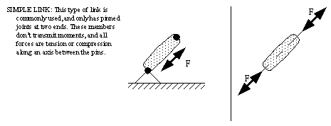
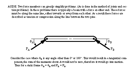
• There are a number of standard load cases that we will encounter. One of the simplest is the two force member discussed before.
egr20940.jpg
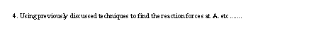
• Three force members can be solved quickly using force triangles, We can also keep in mind that the forces must act concurrently through a common point on the rigid body, or else all three must be parallel.
egr20941.jpg
2.10.1 References
2.7 Hibbeler, R.C., Engineering Mechanics: Statics and Dynamics, 6th edition, MacMillan Publishing Co., New York, USA, 1992.
2.11 Statically Indeterminate
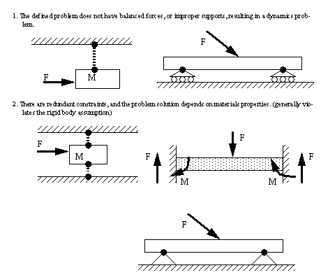
• There are a number of problems that cannot be solved with statics methods. In fact, all problems are inexact, but luckily we can solve some using statics.
• These types of problems often occur when the number of forces known is equal to the number of useful governing equations. This is known as completely constrained.
• When there are more equations than unknowns the problem may be overconstrained.
• When there are fewer equations than unknown forces, the problem may be underconstrained.
• The basic types of cases are,
• be cautious with this class of problems. You may actually be able to calculate a solution, but the answer will not be correct realistically, and mathematically speaking.
2.11.1 Summary
• basic moments and calculations
using normal components
using perpendicular components
using vectors and cross products
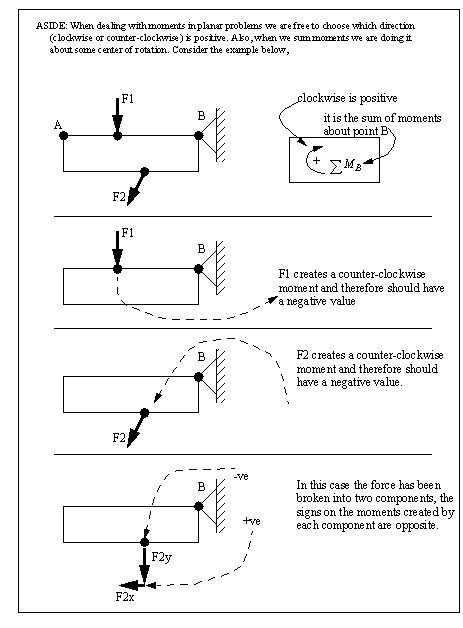
• a review of cross products, and the positive direction for angles/moments
• force couples and moments were shown to be able to freely move about a rigid body.
• a force can be moved away from its axis if a moment is also added.
• mechanical schematic symbols were discussed with applications to statics.
• indeterminate problems
2.11.2 Problems
Problem 2.28 Determine the reactions at A and E.
Answer 2.28
2.11.3 References
2.8 Hibbeler, R.C., Engineering Mechanics: Statics and Dynamics, 6th edition, MacMillan Publishing Co., New York, USA, 1992.
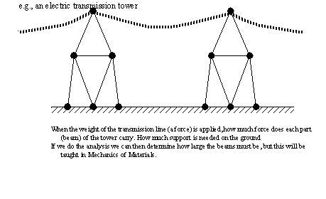
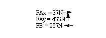
2.12 Trusses and Frames
• We will look at a variety of analysis techniques for trusses and frames. These techniques endeavor to find the internal forces in trusses, and external forces for frames.
• Trusses are at the heart of many engineering projects. We can see one of these in the bridge across the grand river.
egr20908.jpg
• Basically, a truss is a collection of beams joined together to carry simple and complex loads.
• We can see trusses use in cranes,
egr20920.jpg
egr20910.jpg
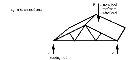
• Trusses are typically made from beams that are joined with gusset plates.
egr20923.jpg
• Other times obvious pin joints are used. Consider the pin joint on the end of the tension member below,
egr20911.jpg
• With these types of problems the tension or compression of the beams/members should be clearly indicated. Materials and structures will not fail at the same load when in tension (necking then fracture), than in compression (buckling).
• We can see a tension member in a bridge with turnbuckles for tensioning,
egr20912.jpg
• The basic assumptions used in most truss and frame problems are,
1. the joints have pinned ends, so the forces exerted by the beam has a direction that is along the line between pins.
2. Forces are exerted at pins, but no moments.
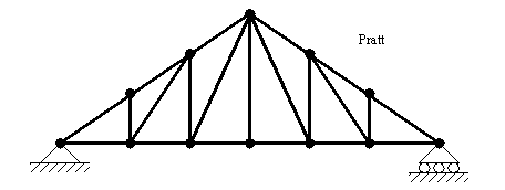
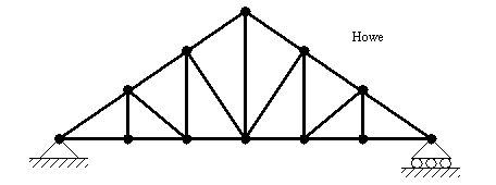
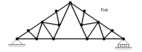
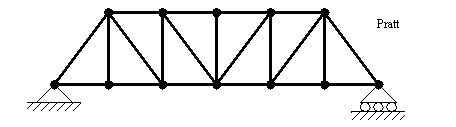
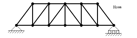
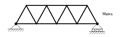
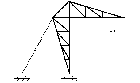
• Types of trusses are shown below,
egr20929.jpg
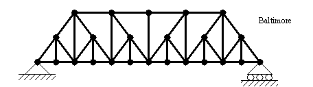
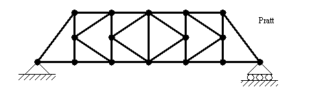
• Picture of other types of trusses can be seen below,
egr20924.jpg
egr20925.jpg
• Many of the methods in this section can also be extended to the analysis of trusses in 3D.
egr20935.jpg
2.12.1 References
2.9 Beer, F.P., Johnson, E.R., Statics & Mechanics of Materials, McGraw-Hill, 1992.
2.10 Hibbeler, R.C., Engineering Mechanics: Statics and Dynamics, 6th edition, MacMillan Publishing Co., New York, USA, 1992.
2.13 Stability of Trusses
• Trusses are composed of beams and pin joints. Generally, if the frame is constructed of only triangles (internally) it will be stable. (not collapse when pushed the wrong way)
• Quite often additional members are added to frames to stiffen it (make it stable), but not to carry loads. We can see such members in a bridge,
egr20913.jpg
• We can predict stability using a basic topological relationship where we look for equality. The equation shown below requires that the truss be composed of simple pinned beams, and when drawn to scale on paper the beams must not cross or touch except at the pinned joints
• We can also verify stability by making nodes that are held in place either by supports, or triangular structures.
• As an example,
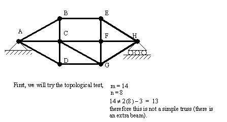
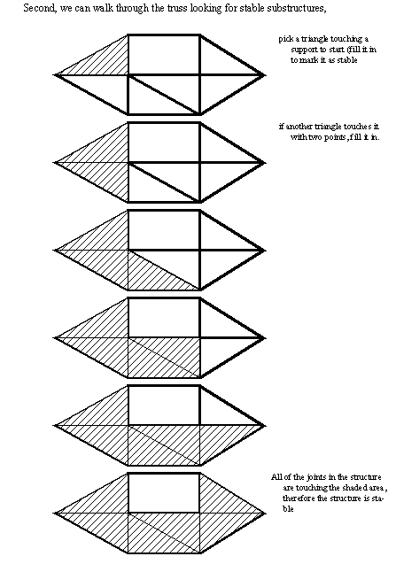
stat0002.wm
2.13.1 References
2.11 Beer, F.P., Johnson, E.R., Statics & Mechanics of Materials, McGraw-Hill, 1992.
2.14 THE METHOD OF JOINTS
• The basic steps when solving problems with the method of joints is,
1. Draw an FBD for each joint as if it is a particle.
2. Solve for the applied forces with the “joint particle” in equilibrium. The simplest joints are often the best to start with.
• We can see an example of a two force member below being used to support a canopy,
egr20909.jpg
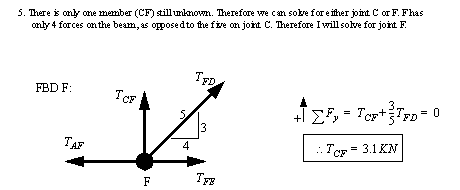
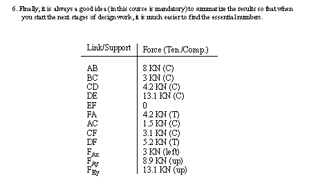
• This method is best shown using a sample problem, ([Hibbeler, 1992], prob 6-7, pg. )
egr20934.jpg
2.14.1 Problems
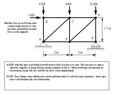
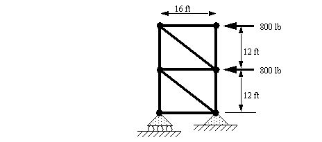
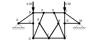
Problem 2.29 Use the method of joints to find the force in each member of the truss below.
Problem 2.30 Determine the force in each member of the truss shown. Indicate tension or compression.
Problem 2.31 Determine the force in each member of the truss shown. Indicate tension or compression.
Problem 2.32 Find the forces in each of the beams of the structure below (indicate tension or compression). Assume all joints are pinned.
Answer 2.32
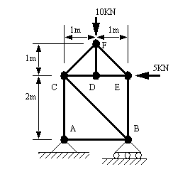
Problem 2.33 For the frame below, find the tension/compression in each member, under the loading conditions given, and assuming all joints are pinned. (Note: you must clearly indicate tension or compression when dealing with this type of problem)
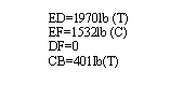
Answer 2.33 EF=515lb(C), BC=515(C), CD=125(C), AB=774(T), AE=401(C), BD=1563(T), BE=625(C), DE=1289(C)
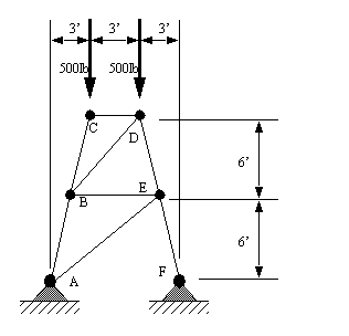
Problem 2.34 Given the frame below, find the tension/compression in each member.
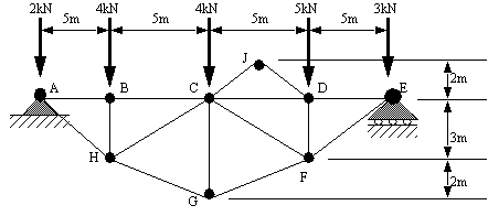
Problem 2.35 Find the forces in each beam of the bridge shown. (As usual, clearly indicate tension or compression)
Answer 2.35
Problem 2.36 Find the tension/compression in each member of the frame below, (HINT: look for 6 zero force members and use symmetry)
Answer 2.36
2.14.2 References
2.12 Beer, F.P., Johnson, E.R., Statics & Mechanics of Materials, McGraw-Hill, 1992.
2.13 Hibbeler, R.C., Engineering Mechanics: Statics and Dynamics, 6th edition, MacMillan Publishing Co., New York, USA, 1992.
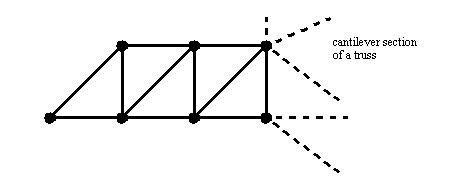
2.15 The Method of Sections
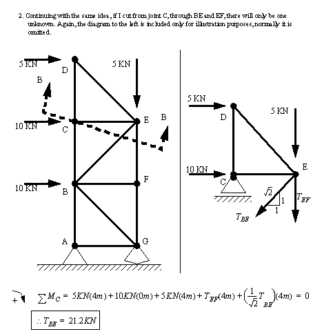
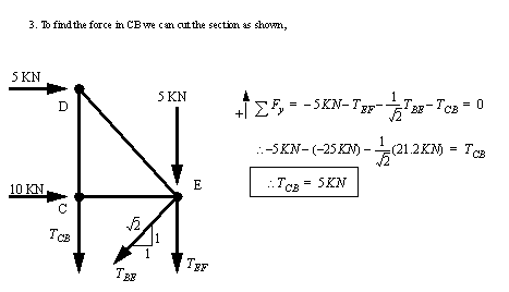
• Basically: cut out a part of a truss, and then treat it as if it is a rigid body. When done wisely, this allows simplified solutions. The alternative is using the method of joints to find all (or many) of the forces in the frame.
• Keep in mind that while moments are very popular with the method of sections, it can also be used for forces as well.
• Consider an example where we want to find forces in a structure, ([Hibbeler, 1992], prob 6-24, pg. )
2.15.1 Problems
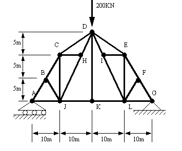
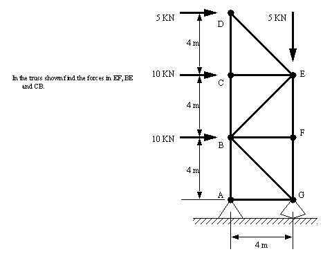
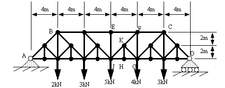
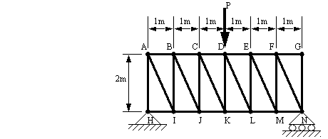
Problem 2.37 Determine the tensions/compressions in members EF, JK and HJ for the bridge truss shown below. The method of sections is recommended.
Problem 2.38 Find the forces in FG and DF (indicate tension or compression). Assume all joints are pinned.
Answer 2.38 AH=1.77kip(C), FG=0)
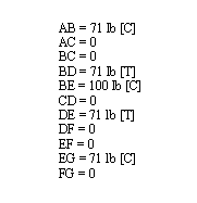
Problem 2.39 In the frame pictured below, find the forces in DE, EF, DF and CB.
Answer 2.39
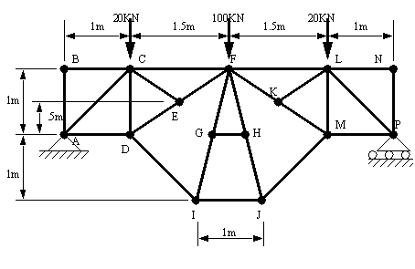
Problem 2.40 Find the forces in members CD, CF, CG. (You will benefit most by using the method of sections to solve this problem)
Answer 2.40 CD= 11.25KN(C), CF= 3.21(T), CG= 6.8(C)
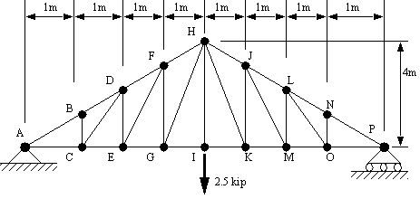
Problem 2.41 In the frame below members DL and EL can support up to 1kip of tension or compression, find the maximum load P that may be applied. (Hint: you could mix the method of joints and sections)
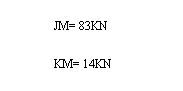
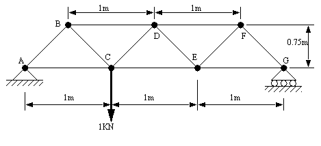
Problem 2.42 Find the forces in JM and KM.
Answer 2.42
Problem 2.43 Find the tension/compression in members CE, DE.
Answer 2.43 CE = .667 KN [T], DE = -.4 KN [C]
2.15.2 References
Hibbeler, R.C., Engineering Mechanics: Statics and Dynamics, 6th edition, MacMillan Publishing Co., New York, USA, 1992.
2.16 Method of Members
• Sometimes we must deal with structures that do not have simple two-force beams, in this case we must use the method of members.
egr20906.jpg
• These structures are commonly called frames, referring to the fact that they have at least one member that has more than two forces. We can see some examples of these members in the picture below,
egr20931.jpg
• In basic terms we are just making good use of free body diagrams, and quite often solving parametric equations. Consider how we could isolate the free body diagrams in the figures below.
egr20930.jpg
• If we were to assume that beams in a truss have a mass, then we would have to use the method of members to solve the problem.
• A sample problem is given to illustrate the method, ([Hibbeler, 1992], prob. 6-60, pg. )
• Now, lets consider a practice problem,
2.16.1 Problems
Problem 2.44 Determine the reactions at A and B.
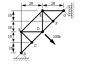
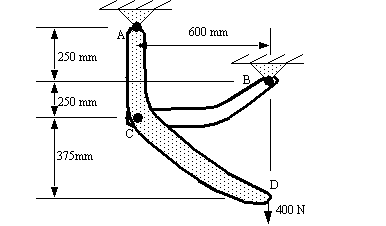
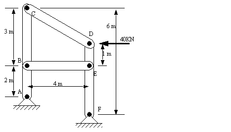
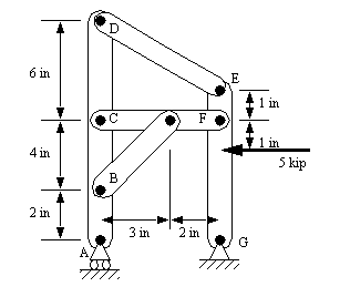
Problem 2.45 In the figure below, determine the force exerted by pin B. The method of members will be most useful.
Problem 2.46 What are the reactions on each of the members (clearly indicate the results on FBDs)?
Answer 2.46 Ax=150N, Ay=150N, Bx=0, By=50N, Cx=150N, Cy=0, Dx=0, Dy=150N
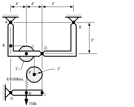
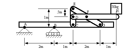
Problem 2.47 Calculate the x- and y-components of the force at D which member AD exerts on member DE. The deflection of the spring in the equilibrium state shown is 2.5 inches. The mass of the members and friction are negligible.
Answer 2.47 70.7N in both
Problem 2.48 The three member frame below is exposed to a load of L=60lb. The beams that the frame is made from weight 8lb/ft. Find the reaction at the base, and find the reaction at each joint and in each member.
Answer 2.48
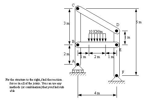
Problem 2.49 For the structure below, find the reaction forces in pins B and E.
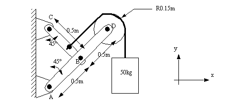
Problem 2.50 Find the forces at all of the pins, and at the supports. (clearly indicate direction using FBDs)
Answer 2.50
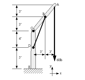
Problem 2.51 Find the forces acting on DCBA at pin D,
Answer 2.51 35.4 kip <135°
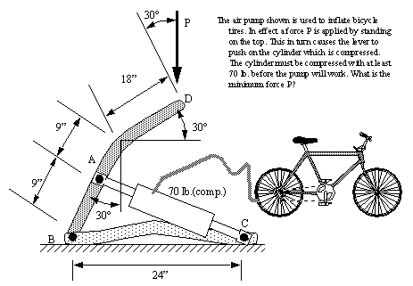
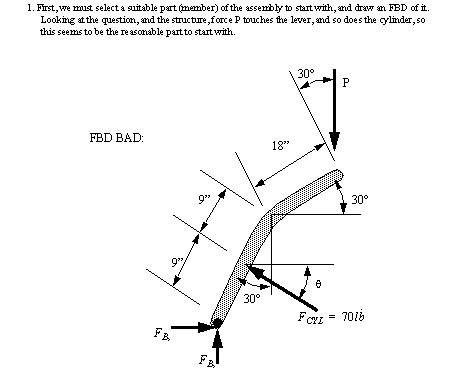
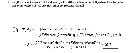
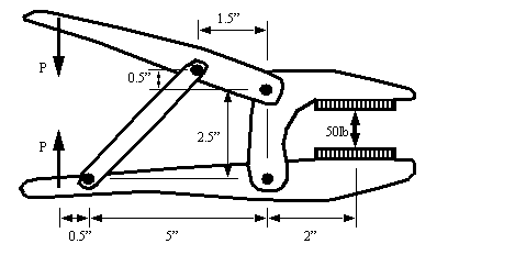
Problem 2.52 We work for a maker of hand tools, and today we are evaluating a new design for vice grip pliers. In the configuration pictured we want a gripping force of 50 lb. between the jaws. How much force P must be applied at the handles to achieve this?
Answer 2.52 P = 12.9 lb.
2.16.2 References
2.14 Hibbeler, R.C., Engineering Mechanics: Statics and Dynamics, 6th edition, MacMillan Publishing Co., New York, USA, 1992.
2.17 Summary
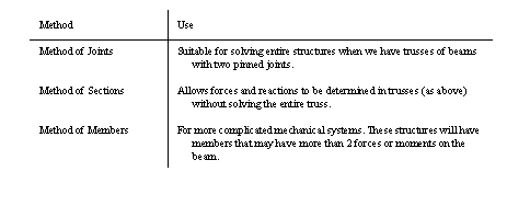
• A simple way to differentiate between the different methods is,
• You are encouraged to mix and match methods in any way that will simplify a solution. For example, in a couple of cases a problem that is being solved by the method of sections could easily use the method of joints in a couple of places.
2.18 Dry Static Friction
• Friction is a force that exists between any two object in contact. This can sometimes work against the engineer, other times it can be of great advantage.
• This natural phenomenon explains the resistance of one object to slide across another when they have common surfaces in contact.
• It is primarily the result of surface roughness, material properties, and if the object is moving.
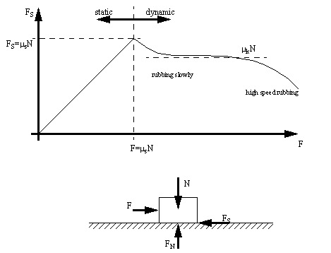
• The graph of applied load versus friction helps illustrate the nature of friction. Notice that while the force is static, the force increases linearly up to the limit. After the object begins moving the force can be approximated with a constant value, using the dynamic coefficient of friction. Note that dynamic friction is shown to be lower that the maximum static friction.
• The basic assumptions that we will use are,
1. the maximum friction force is proportional to the normal force
2. the maximum friction force is not proportional to the area of contact
3. the static friction force is always higher than the dynamic friction force
4. the kinetic friction force is independent of velocity
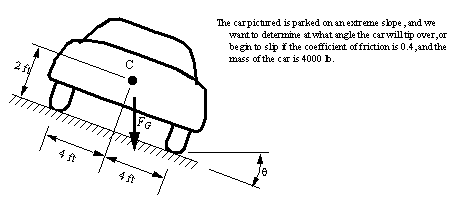
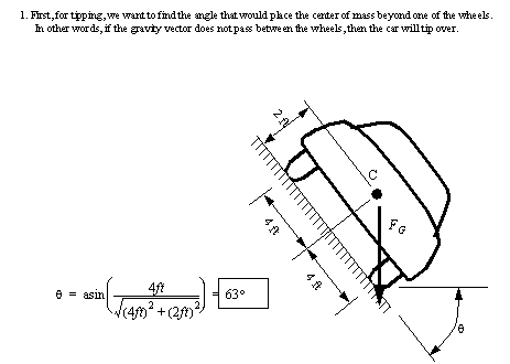
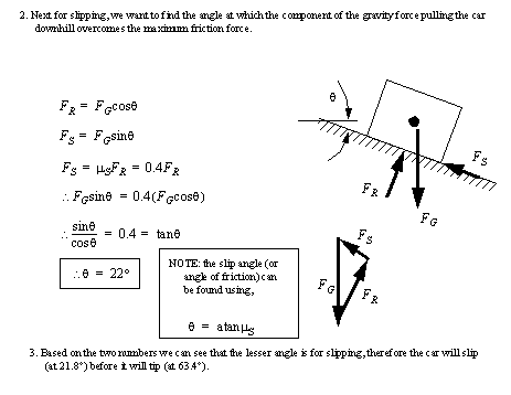
• A couple of the major applications for friction calculations is the determination if an object will slip or tip. The following problem shows a typical application, ([Hibbeler, 1992], prob 8-8, pg. )
• Consider the simple tip/slip problem below,
wm_demos/stat0005.wm
• The general approach to slip-tip problem is,
1. Find the center of gravity for the object.
2. Determine which corner the object is most likely to tip (as if the corner is a pin joint). Sum the moments about the corner. If the sum of moments is equal to zero to block is about to tip. If not equal to zero look at the resulting moment to see if it will cause motion about the corner.
3. Find the component of the gravity and any other non-friction forces acting perpendicular to the surface of contact. Find the components of applied forces acting parallel to the plane of contact.
4. Compare the actual parallel component to the maximum friction force possible. The the resultant is larger than the maximum the block will slip.
*************** More friction examples
2.18.1 Problems
Problem 2.53 We conduct an experiment using the 10 kg. block below on a slope that is being slowly tilted. The block tips over at 20°, and then stops moving, but then it starts to slip at 40°. What is the height ‘h’, and the coefficient of friction?
Answer 2.53 coeff. = 0.84, h = 137 cm
2.18.2 References
2.15 Beer, F.P., Johnson, E.R., Statics & Mechanics of Materials, McGraw-Hill, 1992.
2.16 Hibbeler, R.C., Engineering Mechanics: Statics and Dynamics, 6th edition, MacMillan Publishing Co., New York, USA, 1992.
2.18.3 Applications of Friction
• When dealing with these problems the direction of friction forces must be assigned with care. If the directions are selected backwards, the solutions will be incorrect.
• Before assigning friction forces the impending motion should be analyzed. To do this think of the possible cases that might cause the bodies to start moving: do not assume that all friction surfaces must go into motion. At times this approach may mean that multiple solutions will have to be done to solve a problem.
• The general methods to be followed in these problems involves,
1. Examine the problem to determine impending motion for each individual object, and the overall system. There may be one or more possible cases, each will require a separate solution.
2. Based upon the assumed motion at the points of contact, drawn on friction forces that oppose the motion. Also draw on normal forces.
3. Solve the problem using normal statics (but avoid using sums of moments for friction forces when they don’t act on a clear point).
4. Examine the solution (and compare to others) for anomalies such as normal forces that separate friction surfaces. This will help detemine problems, and to eliminate unreasonable solutions.
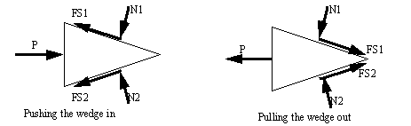
2.18.4 Wedges
• Wedges are a useful engineering tool, and the approach used for wedges also finds its way into other engineering applications.
• A good rule to stick to is that when a wedge is in use, the forces on the faces will both be in the same direction. That is either towards, or away from the point of the wedge.
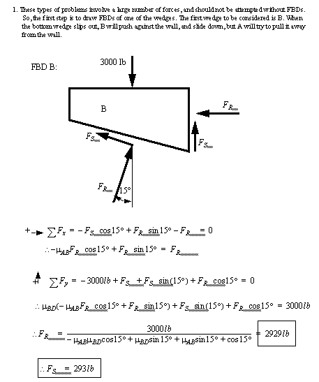
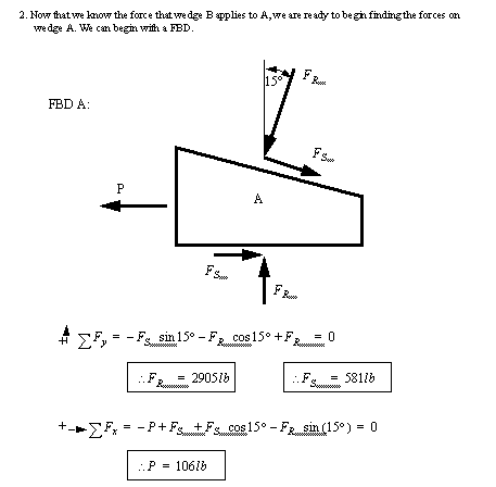
• When solving friction problems we look for friction that is about to let go and start slipping. Keep in mind that not all surfaces will slip, this should be verified after the solution. For all surfaces that slip the friction force will be at the maximum value.
• The example below shows how to deal with a multiple wedge problem. ([Hibbeler, 1992], prob 8-55, pg. )
wm_demos/stat0006.wm
2.18.4.1 - Problems
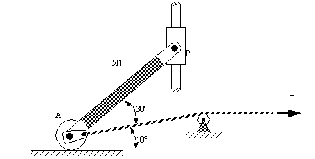
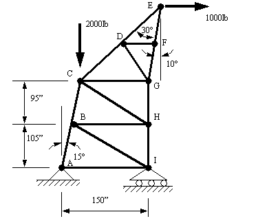
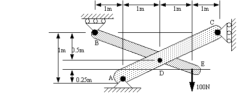
Problem 2.54 A vertical force, F, of 500N acts at one end of a bracket while a wedge is pushed against the other end, as depicted in the diagram below. Given that the weight of the wedge and the bracket can be neglected and that the coefficient of static friction for the contacting surfaces of the wedge is 0.2, determine the horizontal force P required to push the wedge.
Answer 2.54 216 N
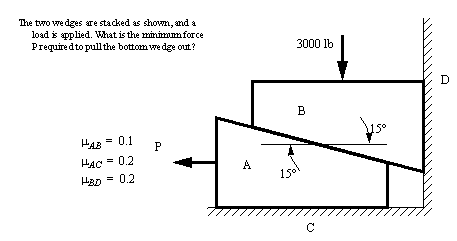
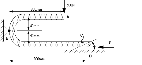
Problem 2.55 The angled bar below has two forces applied that are tending to push it in a counterclockwise direction. These forces are resisted by a wedge that is kept in place by friction (the coefficient of friction is 0.20). determine the force P that is required to pull the block out.
Answer 2.55 6.55KN
wm_demos/stat0007.wm
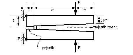
Problem 2.56 We are designing a firing mechanism for a new gun that uses two identical rails that are pressed together to accelerate a projectile. In the figure below we see the two rails at an angle before firing begins. When firing begins, the force ‘F’ will be applied, overcoming the coefficient of friction of 0.05. The length of the projectile is negligible, but it has a wedge shape that matches the rails before firing. What is the initial force ‘F’ that must be applied to the rails before the shot begins to move?
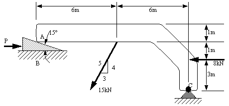
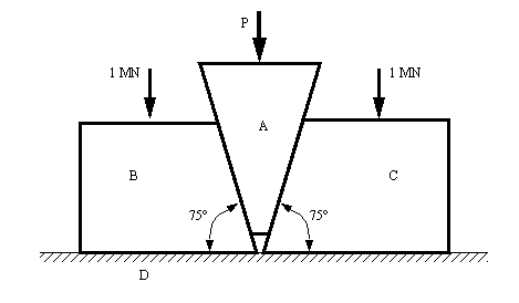
Problem 2.57 What force P will have to be applied to the wedge A to force the blocks B and C apart? You can assume that the coefficient of friction is 0.4 at all points of contact.
Answer 2.57 P = 0.854 MN
2.18.4.2 - References
2.17 Hibbeler, R.C., Engineering Mechanics: Statics and Dynamics, 6th edition, MacMillan Publishing Co., New York, USA, 1992.
2.18.5 Belt Friction
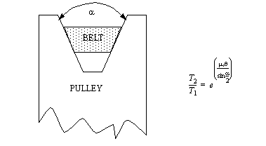
• Belts are a common tool for transmission of forces, motions and velocities.
• If we have a flat belt, it primarily depends on friction to hold it in place.
• The basic rules of static friction still apply for local friction between the belt and the drum, but over the length of the belt the effective normal force changes.
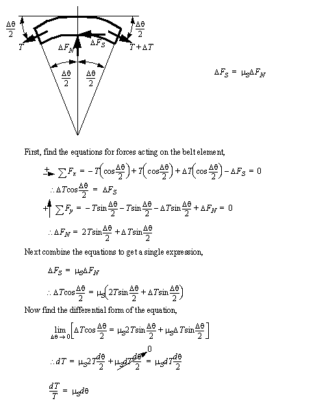
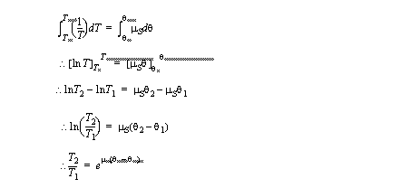
• If we consider one element of the belt we can see an element of friction and a differential of tension.
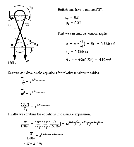
• An example of belt friction is given below (8.123, pg. 40, Beer and Johnston). In this problem the upper drum is moving slowly (this means the belt sticks with static friction), the lower drum allows the belt to slide (the belt slides with dynamic friction). We need to find the force W that will balance the 150lb load on the other side.
• V-belts use the same principle as flat belts, except the friction is increased by the angle of the sides.
2.18.5.1 - Problems
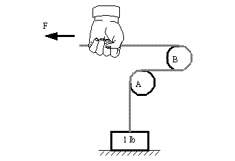
Problem 2.58 A belt is wrapped about drums A and B, both have a radius of 3”. How much force F will have to be applied to lift a weight of 1 lb. if the drums are not moving, and the coefficient of static friction is 0.2?
Answer 2.58 2.57lb
2.18.5.2 - References
2.18 Beer, F.P., Johnson, E.R., Statics & Mechanics of Materials, McGraw-Hill, 1992.