14. Laplace Analysis of the Frequency Domain
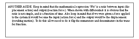
• We can model systems as a ratio between output and input. This allows powerful mathematical manipulation.
14.1 The Laplace Transform
• The Laplace transform allows us to reverse time. And, as you recall from before the inverse of time is frequency. Because we are normally concerned with response, the Laplace transform is much more useful in system analysis.
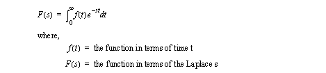
• The basic Laplace transform equations is shown below,
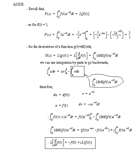
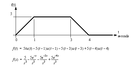
• Consider the examples below,
14.1.1 A Few Transforms
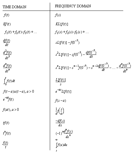
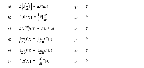
• The basic properties Laplace Transforms for are given below,
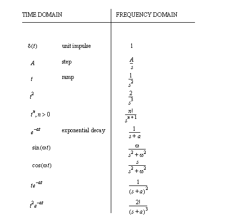
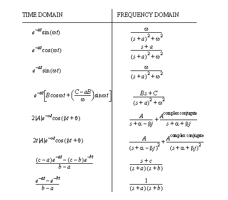
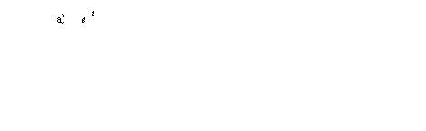
• A set of useful functional Laplace transforms are given below. These are mainly used for converting to and from time ’t’ to the Laplace ’s’.
14.1.2 Impulse Response (or Why Laplace Transforms Work)
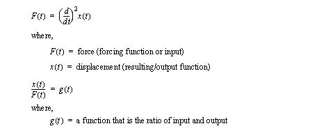
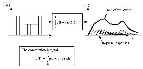
• Consider a system model. That model can be said to have an input (forcing function) and an output (resulting response function).
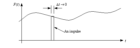
• If we look at an input signal (force here) we can break it into very small segments in time. As the time becomes small we call it an impulse function.
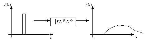
• If we put an impulse into a system the output will be an impulse response.
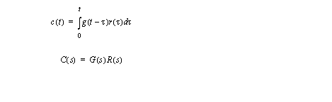
• If we add all of the impulse responses together we will get a total system response. This operation is called convolution.
• The convolution integral can be difficult to deal with because of the time shift. But, the Laplace transform for the convolution integral turns it into a simple multiplication.
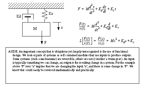
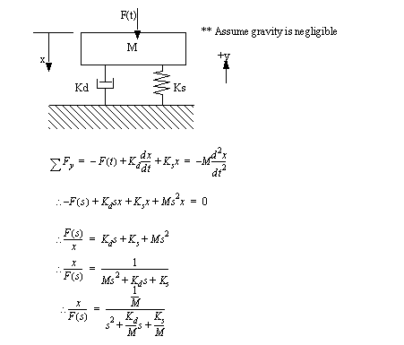
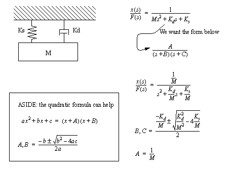
14.2 Modeling Mechanical Systems
• Before doing any sort of analysis of a vibrating system, a system model must be developed. The obvious traditional approach is with differential equations.
14.3 Modeling Electrical Systems
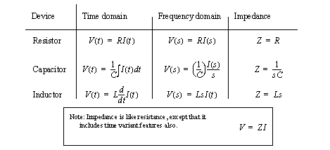
• Consider the basic equations for capacitors, inductors and resistors.
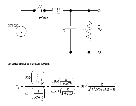
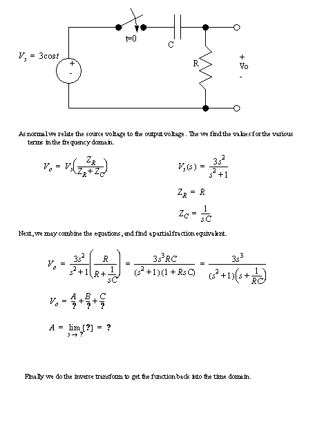
• For the circuit below, the switch is closed at t=0sec,
14.4 Using Laplace Transforms
• The differential equation is in the time domain. By doing a Laplace transform we can move the system into the frequency domain. This makes it much easier to solve complex convolution problems. Without this method, very complex integrals would be required.
• Inputs must in the time domain must also be converted to the frequency domain.
• Normally at this point we would have the input to the system, and the system differential equation. The convolution integral would be used to find the time response, but using Laplace transforms this becomes a simple substitution.
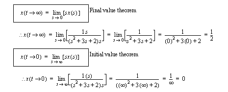
• At this point we have ‘x’ as a function of ‘s’ (later we will see ‘s’ is equivalent to frequency). We can find the initial, and final values (steady state) of ‘x’ using the final value theorem.
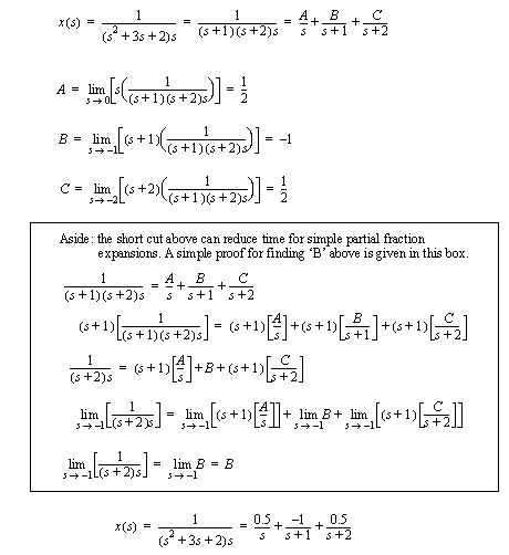
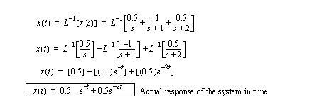
• All that is needed to get the time domain function is an inverse Laplace transform. This is quite often done by using partial fraction expansion of the equations, followed by Inverse Laplace transforms of the simpler parts.
• The terms from the partial fraction expansion are put through an inverse Laplace transform using a lookup table. (A sample table is given later)
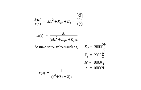
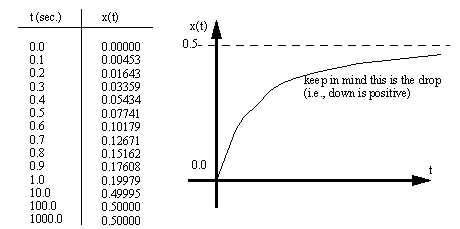
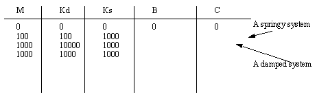
• Some numbers can be calculated to verify this,
• Note that the damper is relatively larger than the spring, therefore no “oscillation”.
• What if the damping approaches 0?
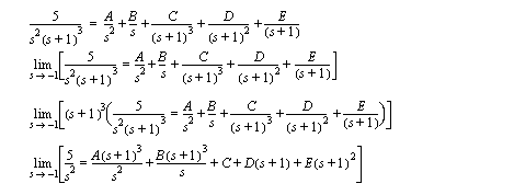
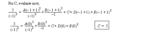
14.4.1 Solving Partial Fractions
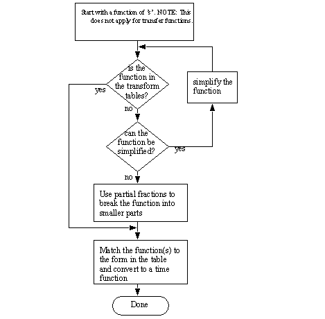
• The following is a flowchart that shows the general method for doing inverse Laplace transforms.
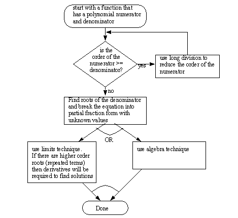
• The next is a flowchart for partial fraction expansions.
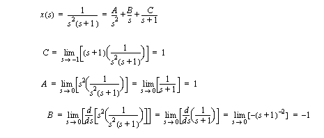
• The partial fraction expansion for,
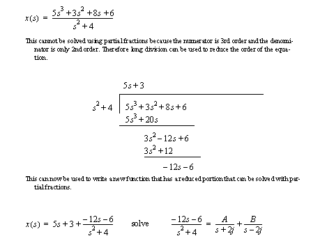
• Consider the example below where the order of the numerator is larger than the denominator.
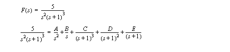
• When the order of the denominator terms is greater than 1 it requires an expanded partial fraction form, as shown below.
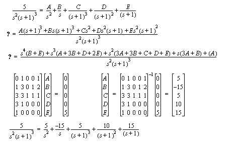
• We can solve the previous problem using the algebra technique.
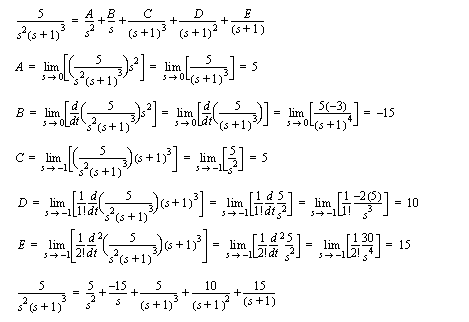
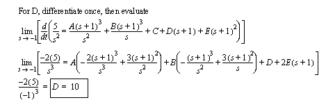
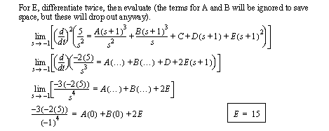
• This problem can also be solved using the limits technique. But, because of the repeated roots we will need to differentiate to find the repeated roots.
• We can prove the technique for the derivatives of the functions.
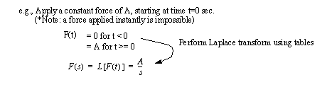
14.4.2 Input Functions
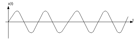
• An example of a complex time function is,
14.4.3 Examples
• These systems tend to vibrate simply. This vibration will often decay naturally. The contrast is the first order system that tends to move towards new equilibrium points without any sort of resonance or vibration.
•
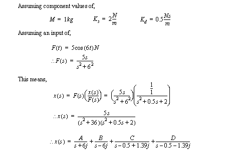
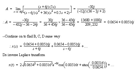
• To continue the example with numerical values,
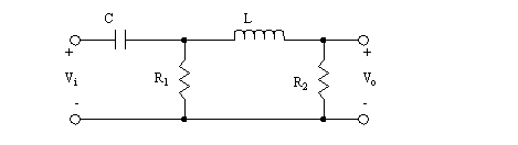
• Consider the circuit below,
14.4.4 Problems
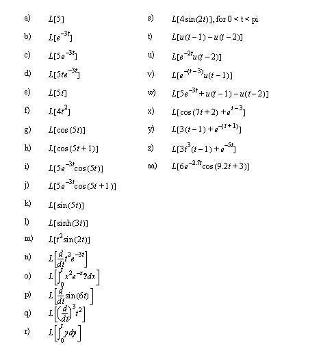
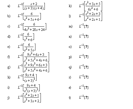
Problem 14.1 Convert the following functions from time to Laplace functions.
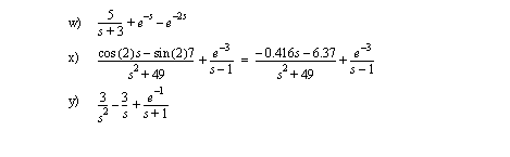
Answer 14.1
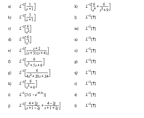
Problem 14.2 Convert the following functions below from the Laplace to time domains.
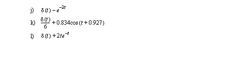
Answer 14.2
Problem 14.3 Convert the following functions below from the laplace to time domains using partial fractions.
Answer 14.3
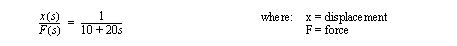
Problem 14.4 Convert the following differential equations to transfer functions.
Problem 14.5 Given the following input functions and transfer functions, find the response in time.
Problem 14.6 Prove the following relationships.
14.5 Fourier Transforms for Steady State Analysis
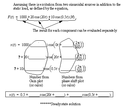
• For the previous mass/damper/spring problem we may now consider what happens if the force oscillates, instead of remaining constant after time=0sec.
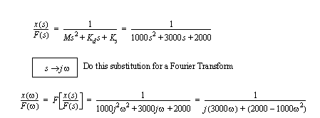
• To find the (steady state) response of the system for a particular frequency of excitation, we may use a Fourier transform. It involves replacing the Laplace ‘s’ as shown below.
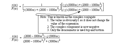
• After the equation is in this form, the next step is to get it in terms of the real and imaginary components. To do this the complex components are eliminated from the denominator by multiplying with the complex conjugate.
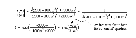
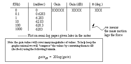
• At this point the expression can be converted to a gain, and phase shift, by converting the real(x)/complex(y) components to polar coordinates (r,θ).
• These can then be calculated, and plotted.
• What does this mean? We can use the graph to find the gain and phase shift at various frequencies. In this example gain is defined as x/F. Therefore F is the input to the system, and x is the resulting output. The gain means that for each unit of F in, there will be gain*F=x out. The input and output are sinusoidal. There is a difference in phase between the input and output wave of θ (the phase angle).
******** continue above with an example
• Steady state solutions are valid after the system has been operating under the set condition for some time, and the initial transient effects have dissipated.
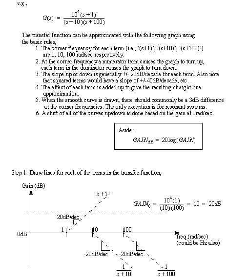
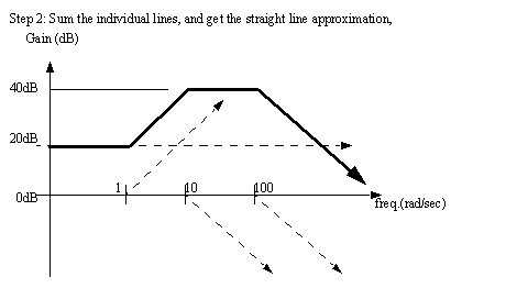
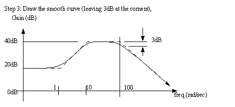
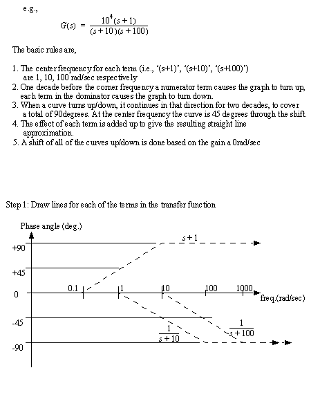
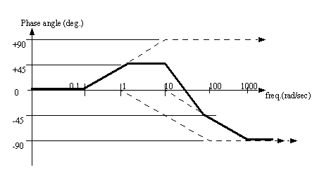
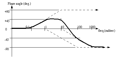
14.6 Bode Plots
• In the previous section we considered using Bode plots to find gain, and phase shift. These plots were calculated one point at a time to construct the graphs, they may also be constructed using approximate techniques. The approximate techniques lose some accuracy, but are very quick.
• Phase angle plots are done in a similar manner,
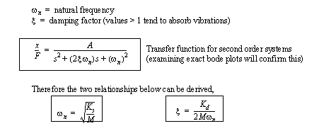
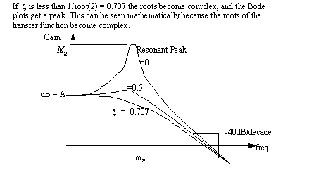
• In the previous examples the bode plots were done for real roots. When there are complex roots we will have a second order system, and we must used the added steps below.
• These generally have an effect on the Bode plot that is very evident.
• Under the influence of damping, the natural frequency will shift slightly,
14.7 Root Locus Analysis
• It is possible to have systems that are unstable. For example, think of a washing machine that vibrates so much that it ‘walks’ across a floor. Or many high speed aircraft that fail due to resonant vibrations.
• To analyze these problems Root-Locus Plots can be used.
• The first step in creating a root-locus plot is to break the equation into roots and poles.
• The next step in creating a root locus plot is to calculate values for the roots, based on varying system parameters.
• These values can then be plotted to give the root locus plot (used for design).
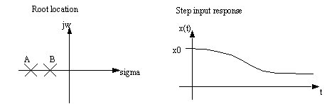
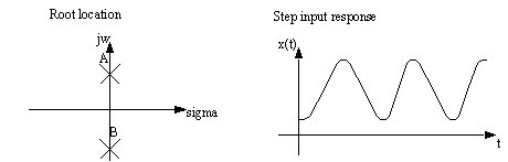
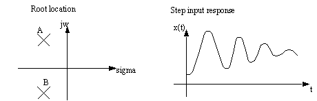
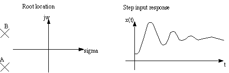
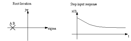
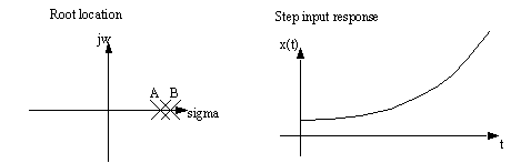
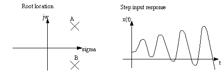
• The use of the root locus plots is to estimate the system performance. For example the system with two roots above will give the following root locus plots, and the corresponding real time responses.
• Note that the last two cases are unstable, and that they have roots in the right hand side of the complex plane
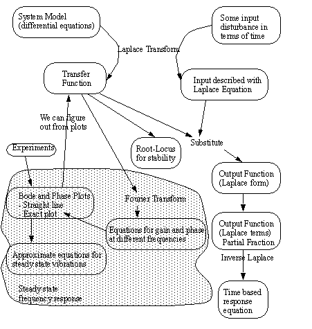
14.8 A Map of the Techniques for Laplacian Analysis
• The following map is to be used to organize the various topics covered in the course.
14.9 Vibrations
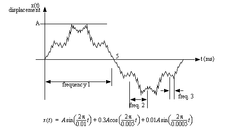
• Vibrations are best thought of many signals mixed together. Each signal has a different frequency and magnitude.
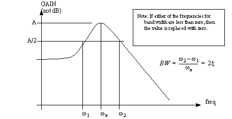
• Bandwidth is a good measure for determining the spread of frequencies that can be passed by a vibrating structure.
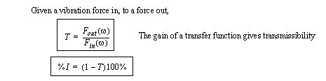
• If we consider a vibration system as having an input, and output we can describe it in terms of transmissibility and isolation.
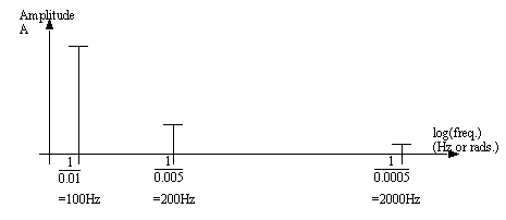
14.10 Signal Spectrum
• A collection of frequency components that have varying magnitudes make up most vibrations.
• But, the math expression is not as important as the spectrum of the signal.
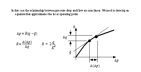
14.11 Non-Linear Elements
• If our models include a device that is non linear we will need to linearize the model before we can proceed.
• A non-linear system can be approximated with a linear equation using the following method.
1. Pick an operating point or range for the component.
2. Find a constant value that relates a change in the input to a change in the output.
3. Develop a linear equation.
4. Use the linear equation in the analysis (Laplace or other)
• Consider the example below,
14.12 Problems
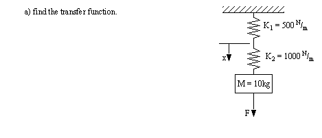
Problem 14.7 Given the transfer function below, develop a mechanical system that it could be for. (Hint: Differential Equations)
Problem 14.8 Given the transfer function, G(s), determine the time response output Y(t) to a step input X(t).
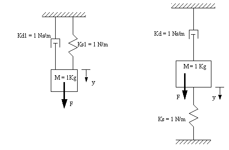
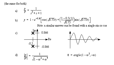
Problem 14.9 Given a mass supported by a spring and damper, find the displacement of the supported mass over time if it is released from neutral at t=0sec, and gravity pulls it downward.
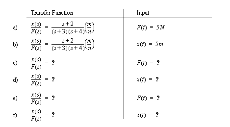
a) find the transfer function x/F (as a Laplace function of time).
b) find the input function F.
c) find the position as a function of ‘s’.
d) do the inverse Laplace transform to find the position as a function of time for Ks = 10N/m, Kd = 5Ns/m, M=10kg.
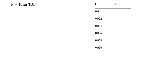
Problem 14.10 The applied force ‘F’ is the input to the system, and the output is the displacement ‘x’.
b) What is the steady state response for an applied force F(t) = 10cos(t + 1) N ?
c) Give the transfer function if ‘x’ is the input.
d) Draw the bode plots.
e) Find x(t), given F(t) = 10N for t >= 0 seconds.
Problem 14.11 Given the transfer function below,
a) draw the straight line approximation of the bode and phase shift plots.
b) determine the steady state output if the input is x(s) = 20 cos(9t+.3)
Problem 14.12 Convert the Laplace function below Y(s) to the time domain Y(t).
Problem 14.13 For the transfer functions below, draw the root locus plots, and draw an approximate time response for each.
Problem 14.14 A system is to be simulated as a single-degree-of-freedom model, with the following parameters: weight 28N, viscous damping coefficient 6N.s/m and stiffness 36N/m. Calculate the undamped natural frequency (Hz) of the system, the damping ratio and describe the type of response you would expect if the mass were displaced and released. What additional damping would be required to make the system critically damped?
Problem 14.15 Four helical compression springs are used at each corner of a piece of equipment. The spring rate is 240 N/m for each spring and the vertical static deflection of the equipment is 10mm. Calculate the weight of the equipment and determine the amount of isolation the springs would afford if the equipment operating frequency is twice the natural frequency of the system.
Answer 14.15 67%
Problem 14.16 A single d.o.f. model with a weight of 1.2 kN and a stiffness of 340 N/m has a steady state harmonic excitation force applied at 95 rpm (revolutions per minute). What is the maximum amount of damping that the system can tolerate if isolation is to be at least 92%?
Problem 14.17 For a maximum transmissibility of 5 at resonance, what would be the required system natural frequency for a steady state forcing frequency of 90Hz to ensure 94% isolation at the operating frequency.
Problem 14.18 For our standard lumped parameter model weight is 36N, stiffness is 2.06*103 N/m and damping coefficient is 100Ns/m. What are the natural frequency (Hz) and damping ratio? What is the bandwidth?
Answer 14.18 fn=3.77Hz, damp.=.575
Problem 14.19 What would the displacement amplitude after 100ms for a system having a natural frequency of 13 rads/sec and a damping ratio of 0.20. Assume an initial displacement of 50mm.
Answer 14.19 0.018m
Problem 14.20 A spring damper system supports a mass of 34N. If it has a spring constant of 20.6N/cm, what is the systems natural frequency?
Answer 14.20 24.37 rad/sec
Problem 14.21 If the damper in 9.1 has a coefficient of 0.1N/(cm/s) what is the damping ratio for the system?
Answer 14.21 0.059
Problem 14.22 V16. If a system, similar to the one in 9.1, is displaced and released, and it moves as described by the following equation, what is the actual damping coefficient ‘a’?
Answer 14.22 a = 6.0
Problem 14.23 If a spring has a deflection of 6 cm when exposed to a static load of 200N, what is the spring constant?
Answer 14.23 33.3N/cm
Problem 14.24 You are given the following differential equation for a spring damper pair.
a) Write the transfer function for the differential equation if the input is F.
b) Use Laplace techniques to find the response of the system to the input given below,
c) Apply the Fourier transform to the transfer function to find magnitude and phase as functions of frequency.
d) Draw a Bode plot for the system using either approximate or exact techniques. Log scale paper is available on the next page
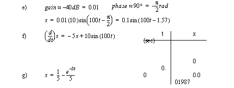
e) Use the Bode plot to find the response to,
f) Put the differential equation in state variable form and use a calculator to find values in time for the given input.
g) Give the expected ‘x’ response of this first order system to a step function input for force F=1N for t>0 if the system starts at rest. Hint: Use the canonical form.
Answer 14.24
Problem 14.25 For each of the systems below,
a) write the differential equation and convert it to a transfer function.
b) if the input force is a step function of magnitude 1N, convert the input to a Laplace form, and use it to find the time response for ‘y’.
c) Draw the poles on a real-complex plane.
d) Apply the Fourier transform function and make it a function of frequency. Plot the Gain and magnitude as a function of frequency.
Answer 14.25
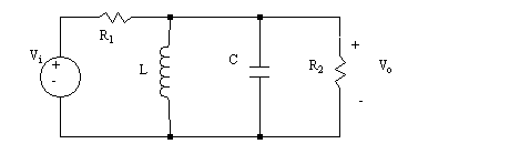
Problem 14.26 1. Develop differential equations and then transfer functions for the mechanical and electrical systems below.
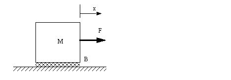
a) There is viscous damping between the block and the ground. A force is applied to cause the mass the accelerate.
b)
Problem 14.27 2. The following differential equation is supplied, with initial conditions.
a) Write the equation in state variable form.
b) Convert the differential equation to the Laplace domain, including initial conditions. Solve to find the time response to the given input using Laplace transforms.
c) Solve the differential equation using calculus techniques.
d) Find the frequency response (gain and phase) for the transfer function using the Fourier transform. Roughly sketch the bode plots.
Problem 14.28 3. a) Write the differential equations for the system pictured below.
b) Put the equations in state variable form.
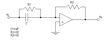
c) Use mathcad to find the ratio between input and output voltages for a range of frequencies. The general method is put in a voltage such as Vi=1sin(___t), and see what the magnitude of the output is. Divide the magnitude of the output sine wave by the input magnitude. Note: This should act as a high pass or low pass filter.
d) Plot a graph of gain against the frequency of the input.
Problem 14.29 4. Find the transfer functions for the systems below.
a) Vi is the input and Vo is the output.
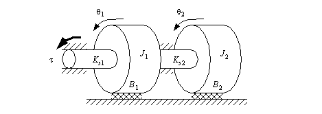
b) Here the input is a torque, and the output is the angle of the second mass.
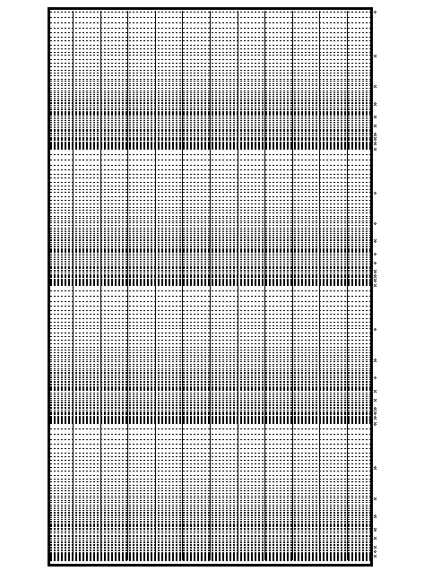
14.13 Log Scale Graph Paper
Please notice that there are a few sheets of 2 and 4 cycle log paper attached, make additional copies if required, and if more cycles are required, sheets can be cut and pasted together. Also note that better semi-log paper can be purchased at technical bookstores, as well at most large office supply stores.
14.14 References
14.1 Irwin, J.D., and Graf, E.R., Industrial Noise and Vibration Control, Prentice Hall Publishers, 1979.
14.2 Close, C.M. and Frederick, D.K., “Modeling and Analysis of Dynamic Systems, second edition, John Wiley and Sons, Inc., 1995.