1.1 BASIC PLCs
• A Programmable Controller (PC) is an input/output processing computer.
• Advantages of PLCs,
- cost effective for complex systems
- flexible
- computational abilities
- trouble shooting aids
- reliable
• Ladder logic was originally introduced to mimic relay logic.
• A thorough review of the research literature is available in Sobh et. al. [1994].
• The PLC can be programmed like other computers using specialized “languages”.
- Ladder Logic - A programming technique using a ladder like structure. This was originally adopted because of its similarity to relay logic diagrams to ease its acceptance in manufacturing facilities. The ladder approach is somewhat limited by the lack of loops, etc. (Uses JIC standards)
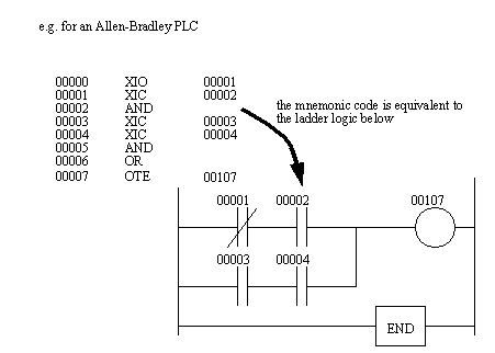
- Mnemonic - instructions and opcodes, similar to assembly language. More involved to program, but also more flexible than ladder logic.
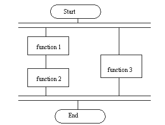
- Sequential Function Charts (SFC) - an alternative to a flowchart method for concurrent operations. Currently this is not widely used, but it (or a similar version) should become more prevalent in the upcoming years.
• Structured text allows programs that are similar to high level languages such as BASIC.
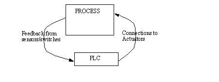
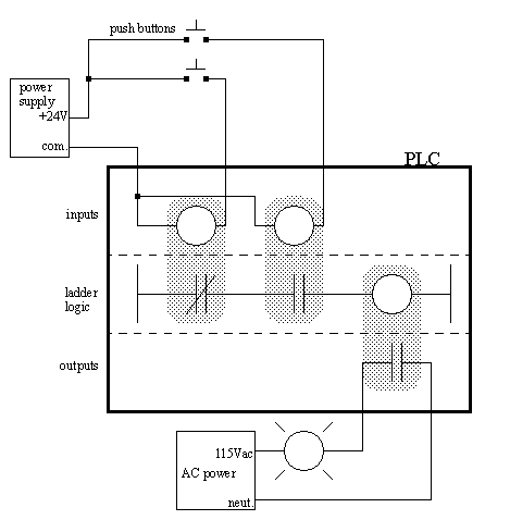
1.1.1 PLC Connections
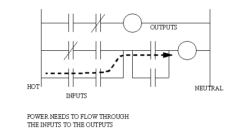
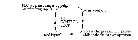
• The PLC continuously scans the inputs, and changes the outputs.
• The Process can be anything - a large press, a car, a security door, a blast furnace.
• As inputs change (e.g. a start button) the outputs will be changed. This will cause the process to change, and new inputs to the PLC will be received.
1.1.2 Ladder Logic
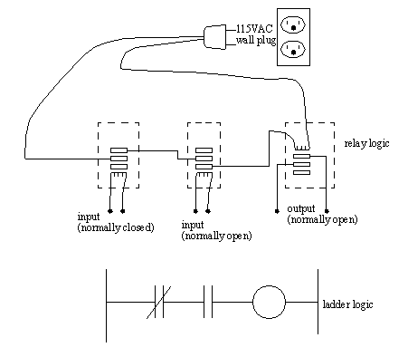
• As mentioned before, ladder logic has been developed to mimic relay logic. This was done originally to make the computer more acceptable to companies and employees. Original efforts resisted the use of computers because they required new skills and approaches, but the use of ladder logic allowed a much smaller paradigm shift, therefore making them more acceptable.
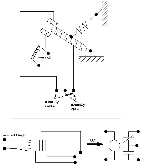
• Original Relay Ladder Logic diagrams show how to hook-up inputs to run outputs.
- Relay - An input coil uses a voltage/current to create a magnetic field. As the coil becomes magnetic it pulls a metal switch (or reed) towards it, and makes an electrical contact. The contact that closes when the coil is energized is normally open. There is a contact that the reed touches without the coil energized is called the normally closed contact. Relays are used to let one power source close a switch for another (often high current) power source, while keeping them isolated.
- A Circuit - A mix of inputs and outputs allows logical selection of a device.
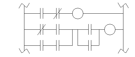
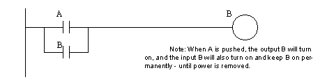
• many relays also have multiple outputs (throws) and this allows an output relay to also be an input simultaneously. The circuit shown below is an example of this. It is called a seal in circuit.
1.1.3 Ladder Logic Outputs
• The outputs allow switches to close that supply/cut-off power to control devices.
• Ladder logic indicates what to do with the output, regardless of what is hooked up -- The programmer and electrician that connect the PLC are responsible for that.
• Outputs can go to electrical outputs, or to memory.
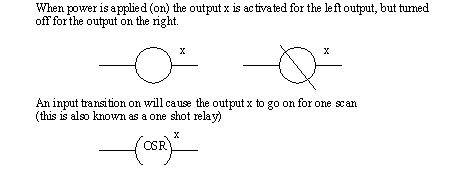
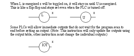
• Output symbols,
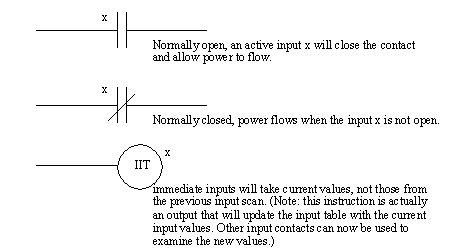
1.1.4 Ladder Logic Inputs
• Contact coils are used to connect the PLC power lines to drive the outputs.
• The inputs can come from electrical inputs, or memory locations