1.1.1 Block Diagrams
• Blocks in the block diagrams will transform energy
• Summation points (circles) will compare, or add quantities
• These diagrams can be used to design physical systems, and the subcomponents

• Control systems for devices can be described using block diagrams
• Two main approaches to actuator control
1. Torque controlled by current amplifiers driving a motor
2. Speed controlled by voltage using a voltage amplifier
• Torque control maintains a constant desired torque which is desirable in assembly operations. Also maintains constant force (gripper) without drawing additional power. A disadvantage occurs when the required torque is less than the applied torque. This causes higher acceleration and velocities resulting in the non-zero velocity at the target point and inaccuracies. If the inertia is higher than expected the resisting torque would be larger than the constant applied torque causing slow motion, and loss of production time.
• Speed control is less affected by variations in inertia and the time to reach the target point is not affected. The approach is slow and smooth. Problems occur because torque is not controlled. Motor draws from the voltage amplifier the current required to overcome the disturbance. If the robot encounters a rigid obstacle the amplifiers fuse could burn-out. This makes it unsuitable for assembly tasks such as press fitting where a constant force is required, but it is good for spray painting and seam welding.
• The choice of control depends on the application and the environment
• Inputs to velocity controlled robots from the computer are,
a) A sequence of pulses - each pulse generates one BRU (Basic Resolution Unit). The number of pulses represents position and the pulse frequency is proportional to velocity
b) a binary word as samples data - used in most modern robots with both velocity-controlled and torque controlled systems.
• Blocks in the block diagrams will transform energy
• Summation points (circles) will compare, or add quantities
• These diagrams can be used to design physical systems, and the subcomponents

• although these systems are not linear, we can approximate them with linear models and measures.
** Note: many of the concepts in this section apply to other controls sections as well
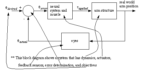
• A simple feedback control loop is shown below

• If we expand the above system to system that has second order response we get a system like that below,

• We can even develop control systems that will compensate for non-linear effects, such as gravity,

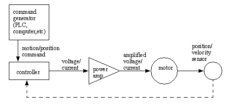
• To drive a motor (beyond just turning it on) we will need a power amplifier, and typically a controller.

• Servo loops with DC motors and encoder/resolver feedback are used for positions or velocities
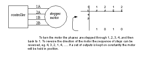
• Stepper motors often have no feedback. They use four wires changed in pattern to turn the rotor.

• Basic types of motor controllers include,
translators - the user indicates maximum velocity and acceleration and a distance to move
indexer - the user indicates direction and number of steps to take
microstepping - each step is subdivided into smaller steps to give more resolution
• These motors do not provide much torque, but they are excellent for positioning applications.
