1.2.1 Basic Robotic Systems
• The basic components of a robot are,
Structure - the mechanical structure (links, base, etc). This requires a great deal of mass to provide enough structural rigidity to ensure minimum accuracy under varied payloads.
Actuators - The motors, cylinders, etc. that drive the robot joints. This might also include mechanisms for a transmission, locking, etc.
Control Computer - This computer interfaces with the user, and in turn controls the robot joints.
End of Arm Tooling (EOAT) - The tooling is provided be the user, and is designed for specific tasks.
Teach pendant - One popular method for programming the robot. This is a small hand held device that can direct motion of the robot, record points in motion sequences, and begin replay of sequences. More advance pendants include more functionality.
1.2.2 Types of Robots
• Robots come in a wide variety of shapes, and configurations.
• The major classes of robots include,
arms - fixed in place, but can reach and manipulate parts and tools
mobile - these robots are free to move
1.2.2.1 - Robotic Arms
• Typical joint types are,
Revolute - rotary joints often driven by electric motors and chain/belt/gear transmissions, or by hydraulic cylinders and levers.
Prismatic - slider joints in which the link is supported on a linear slider bearing, and linearly actuated by ball screws and motors or cylinders.
• Basic configurations are,
Cartesian/Rectilinear/Gantry - Positioning is done in the workspace with prismatic joints. This configuration is well used when a large workspace must be covered, or when consistent accuracy is expected from the robot.
Cylindrical - The robot has a revolute motion about a base, a prismatic joint for height, and a prismatic joint for radius. This robot is well suited to round workspaces.
Spherical - Two revolute joints and one prismatic joint allow the robot to point in many directions, and then reach out some radial distance.
Articulated/Jointed Spherical/Revolute - The robot uses 3 revolute joints to position the robot. Generally the work volume is spherical. This robot most resembles the human arm, with a waist, shoulder, elbow, wrist.
Scara (Selective Compliance Arm for Robotic Assembly) - This robot conforms to cylindrical coordinates, but the radius and rotation is obtained by a two planar links with revolute joints.
1.2.2.2 - Autonomous/Mobile Robots
• The robots discussed up to this point have concerned ‘arms’ that are fixed to the floor. Another important class of robots are autonomous, and free to move about the workspace.
• Typical applications are,
- nuclear accident cleanup
- planetary exploration
- Automatic Guided Vehicles in factories
- mail delivery
1.2.2.2.1 - Automatic Guided Vehicles (AGVs)
• These are typically wheeled robots that carry payloads through a factory.
• They navigate using,
- wires embedded in floors
- light sources or reflectors
- colored tapes on the floor
1.2.3 Commercial Robots
• Some specifications for commercial robots are given below
1.2.3.1 - Seiko RT 3000 Manipulator
• In general
Degrees of freedom 4
Maximum payload 5kg (11 lb)
Repeatability (based on constant temp., load, speed) +/-0.025mm (+/- 0.001 in.)
Weight 108kg (237 lb)
Operating Temperature 0C to 40C (32F to 104F)
Humidity (based on constant temp. load, speed) 20% to 90%
Power Requirements 200-240 VAC
Other 50-70 psig air
• A-axis
motion revolute
Range +/-145 degrees
Resolution 0.005 deg.
Speed
max. speed 150 deg/sec
max. torque 383. in.lbs
• Z-axis
motion linear
Range 4.72 in (120mm)
Resolution 0.0005 in (0.012mm)
Speed
max. speed 14 in/sec (360 mm/sec)
max. force 23.3-35.2 lbs (10.6-16.0 kg)
• R-axis
motion linear
Range 11.8 in (300mm)
Resolution 0.001 in (0.025mm)
Speed
max. speed 29.5 in/sec (750 mm/sec)
max. force 40 lbs
• T-axis
motion revolute
Range 290 degrees
Resolution 0.003 deg.
Speed
max. speed 90 deg/sec
max. torque 358. in.lbs
• The workspace is pictured below,
1.2.3.2 - DARL Programs
• All DARL comments follow ’ at any position on a line.
• Statements are ended with a colon, and as long as colons are used, more than one statement can be used on a line.
• Line numbering is required for DARL programs.
• Dimensions are given in millimeters in the programs.
• Commas and spaces are treated as equivalent.
• A sample program is given below with comments for explanation,

1.2.3.2.1 - Language Examples
• First, points can be defined in programs, they can also be defined by moving the robot to the location and storing the value. This allows the robot to accurately find points without measuring. It also means that points location values don’t need to appear in programs, they are stored in memory.
• A example that uses for-next, if-then, goto and gosub-return commands is shown below. These commands are very standard in their use.
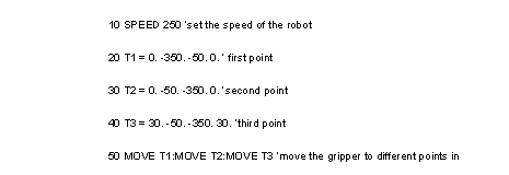
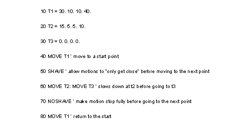
• A example that uses motion is shown below. The ‘move’ command causes a motion to another point by only turning the needed joints. ‘moves’ causes a more complex motion resulting in a straight line tool motion between points. ‘movec’ allows a circular interpolation dictated by three points (the start, and the two given). The shave command forces the robot to fully complete a motion and stop before going to the next point. The sync command will move the robot, but keep the gripper in the original position relative to the real world.

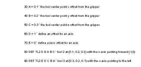
• A example that defines tool location offsets is shown below. This is particularly useful for a robot that has more than one tool attached. The normal tool location is on the end of the arm. With multiple tools attached we will have multiple tool center points. We can have a tool definition for each one of these. Note that the x-axis is the normal forward for the tool. The tool axis can only be changed in the x-y plane (or the plane perpendicular to the gripper rotation).

• A example that uses pallet commands is shown below. Basically a pallet allows us to create an array of points (it does the calculations). We can then give a location on a pallet and move to that point. The basic pallet definition requires that we indicate the number of rows and columns. We also need to define the physical locations of the rows and columns. We do this by giving an origin point, and then defining where the first row and column end. To use the pallet location we can simply refer to the pallet location index.
• A example that defines and uses new frames is shown below. We define a new frame of reference by using points. The first point becomes the new origin. The second point determines where the new x-axis points. The z-axis remains vertical, and the y-axis is shifted appropriately.
• A example that uses simple inputs and outputs is shown below. Note that there are two connectors for I/O. The main or ‘E’xternal connector is on the main controller box. The other I/O lines are on the ‘G’ripper. We can check the states of inputs and set the states of outputs. The ‘+’ sign indicates inputs/outputs high (5v) and the ‘-’ sign indicates low (0V). The ranges for input points are ie0-ie15, ig0-ig7, and for output points oe0-15, og0-7. The search command allows us to move the robot until an input is activated. This is useful when attempting to find a part by touching it.
1.2.3.2.2 - Commands Summary
• A summary of the commands is given below,
1.2.3.3 - Mitsubishi RV-M1 Manipulator
• In general
Degrees of freedom 5
Maximum payload 1kg (2.2 lb)
Repeatability (based on constant temp., load, speed) +/- 0.3mm
Weight 19kg (42 lb)
Operating Temperature 5C to 40C
Humidity (based on constant temp. load, speed) 10% to 85%
Power Requirements 120/220/230/240 VAC
Other 50-70 psig air
• waist
motion revolute
Range 300 degrees
Resolution ?? deg.
Speed
max. speed 120 deg/sec
max. torque ?? in.lbs
• shoulder
motion revolute
Range 130 degrees
Resolution ?? deg.
Speed
max. speed 72 deg/sec
max. torque ?? in.lbs
• elbow
motion revolute
Range 110 degrees
Resolution ?? deg.
Speed
max. speed 109 deg/sec
max. torque ?? in.lbs
• wrist pitch
motion revolute
Range +/-90 degrees
Resolution ?? deg.
Speed
max. speed 100 deg/sec
max. torque ?? in.lbs
• wrist roll
motion revolute
Range +/-180 degrees
Resolution ?? deg.
Speed
max. speed 163 deg/sec
max. torque ?? in.lbs
• The workspace is pictured below,
1.2.3.4 - Movemaster Programs
• All comments follow a semi-colon at any position on a line
• Statements are ended with a colon, and as long as colons are used, more than one statement can be used on a line.
• Line numbering is required.
• Dimensions are given in millimeters in the programs.
• A sample program is given below with comments for explanation,

1.2.3.4.1 - Language Examples
• The example below shows how points are defined and used. Please be aware that point location values are not normally defined in a program. Normally they are programmed by hand, and then when the program is run, it refers to them by number (from 1 to 629)
• The example below shows how we can define and use pallets. The definition of a pallet covers a number of lines to define the pallet size and then the location. We must also define points to indicate where the pallet lies in space. For the example below these points would have to be position numbers 20 (pallet origin), 21 (origin to end of first column), 22 (origin to end of first row), 23 (origin to diagonal corner of pallet). Note: if using pallet #3 these counters would be 30-33, and point 3 would move.
• The example below shows some of the position commands. These positions are normally defined outside the program by moving the robot to desired locations. These positions are not always absolute, and in some cases will act as displacement vectors.
• The example below shows some of the counter and branching functions. These tend to use a status register approach - for example, a value to be compared will be loaded on one line, the next line will compare it and a branch instruction will occur on the specified condition. For-next loops have been constructed as part of this example.
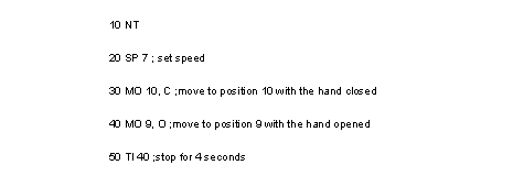
• The example below shows how to use various gripper and I/O functions. There are eight input bits and 8 output bits available.
1.2.3.4.2 - Command Summary
• A summary of the motion commands is given below,
• A summary of the program control commands is given below,
• A summary of the IO commands is given below,
1.2.3.5 - IBM 7535 Manipulator
• In general
Degrees of freedom 4
Maximum payload 6kg (13.2 lb)
Repeatability (based on constant temp., load, speed) +/-0.05mm (+/- 0.002 in.)
Weight 99kg (218 lb)
Operating Temperature 10C to 40.6C (50F to 106F)
Humidity (based on constant temp. load, speed) 8% to 80%
• Theta 1 axis
motion revolute
Range 0 to 200 degrees +/- 1deg.
Resolution 0.00459 deg.
Low speed (note: this is set by a switch)
max. speed 700 mm/sec (28 in./sec)
max. load 6 kg(13.2 lb)
Medium speed
max. speed 1100 mm/sec (43 in./sec)
max. load 6 kg(13.2 lb)
High speed
max. speed 1450 mm/sec (57 in./sec)
max. load 1 kg(2.2 lb)
• Theta 2 axis
motion revolute
Range 0 to 160 degrees +/- 1deg.
Resolution 0.009 deg.
Low speed (note: this is set by a switch)
max. speed 525 mm/sec (21 in./sec)
max. load 6 kg(13.2 lb)
Medium speed
max. speed 825 mm/sec (32 in./sec)
max. load 6 kg(13.2 lb)
High speed
max. speed 1000 mm/sec (39 in./sec)
max. load 1 kg(2.2 lb)
• Roll axis
motion revolute
Range +/- 180 degrees +/- 1.5 deg.
Holding Torque 35 kg-cm (30.4 in.-lb.)
Maximum load centered on Z-Axis 6 kg (13.2 lb)
Maximum speed 3.7 rad/sec (210 deg./sec. +/-5%)
Rotating Torque 14 kg-cm (12.2 in-lb)
Max. load inertia 0.1 kg-m**2 (0.074 slug-ft**2)
(Note: effects of off centre loads not
considered, and lower maximum)
Resolution 0.36 deg.
• Z-Axis
motion prismatic
Range 75 mm (2.95 in.)
Maximum Payload 6.0 kg (13.2 lb)
Resolution Not Applicable
• Compressed Air
Maximum Pressure 6 kg/cm**2 (85 psig)
Conditioning Must be moisture free, as through a
moisture separator, and filtered with
regulator.
• The workspace is shown below,
1.2.3.6 - AML Programs
• All AML comments start with two dashes ‘--’ at any position on a line
• Statements are ended with a semi-colon, and as long as semi-colons are used, more than one statement can be used on a line.
• Line numbering is done by the AML Editor
• the free form variables/identifiers must: start with a letter; be up to 72 characters in length; use letters numbers and underscores, except in the last position.
• Statements have the general form,
• A sample program is given below with comments for explanation,
• A summary of the commands is given below,
• A summary of some of the keywords is,
1.2.3.7 - ASEA IRB-1000
• In general
maximum payload (for a 200mm tool offset) 6 kg
Maximum moment of inertia 2.5 Nm (dynamic)
Maximum static moment 12 Nm (static)
weight 125 kg
accuracy at wrist +/- 0.20mm
• Axis 1
joint type revolute
range 340 deg.
speed 95 deg/sec
actuator servo
• Axis 2
joint type revolute
range +/-40 deg.
speed 0.75 m/sec
actuator servo
• Axis 3
joint type revolute
range +/-25 deg. to -40 deg.
speed 1.1 m/s
actuator servo
• Axis 4
joint type revolute
range +/- 90 deg.
speed 115 deg/sec.
actuator servo
• Axis 5
joint type revolute
range +/- 180 deg.
speed 195 deg/sec
actuator servo
• Gripper
Pneumatic 2 solenoid valves are located in the
upper arm, and can be operated by
the programs.
electrical There is a four pole electrical outlet
in the upper arm for use with more
advanced grippers having search
functions.
1.2.4 Unimation Puma (360, 550, 560 Series)
• In general,
- an articulated arm with 3 dof for positioning, and 3 dof for orientation
- left/right arm configurations are possible
- uses DC servo motors for drive
- uses 110-130 VAC, 50-60Hz, 1.5KW
- weight 120 lb
- repeatability 0.004in
- RS-232C port for dumb terminal
- 32 parallel I/O lines
- memory 16K
- programming language is VAL
• joint 1 (Waist)
joint type revolute
range 315°
max slew rate 1.9 rad/sec.
resolution .0001 rad/bit
maximum static torque 9.9Nm
• joint 2 (Shoulder)
joint type revolute
range 320°
max slew rate 1.8 rad/sec.
resolution .00009 rad/bit
maximum static torque 14.9Nm
• joint 3 (Elbow)
joint type revolute
range 300°
max slew rate 2.6 rad/sec.
resolution .000146 rad/bit
maximum static torque 9.1Nm
• joint 4 (Wrist Rotation)
joint type revolute
range 575°
max slew rate 8.7 rad/sec.
resolution .000181 rad/bit
maximum static torque 1.5Nm
• joint 5 (Wrist Bend)
joint type revolute
range 235°
max slew rate 5.6 rad/sec.
resolution .000199 rad/bit
maximum static torque 1.4Nm
• joint 6 (Flange Rotation)
joint type revolute
range 525°
max slew rate 5.2 rad/sec.
resolution .000247 rad/bit
maximum static torque 1.1Nm