1.4 MULTI-CONTROLLER SYSTEMS
• It can sometimes be helpful to have more than one controller in a system.
• In feedforward controllers we have one controller to deal with an input value, and a second to control error.
• In cascade control we break the control into segments, that take advantage of readings within the process.
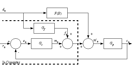
1.4.1 Disturbance Feedforward
• When a system has a disturbance that can be measured we can add a controller that specifically compensates.
• The figure below shows a feedforward disturbance controller,
• In this case ‘F(B)’ is a function of how the disturbance actually effects the system. But ‘Gf’ is the controller to compensate. First, we need a model of ‘F(B)’. Next the controller ‘Gf’ is,
• The error controller is designed as if the disturbance is not present.
• This system is well suited to systems with large measurable disturbances. For example we could measure cutting force, and adapt an axis controller on a CNC machine.
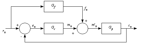
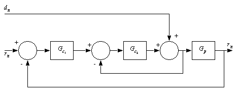
1.4.2 Command Feedforward
• By separating out error control, and process modeling functions we can make a system that is more accurate, with reduced steady state error.
• This technique may be used when we have a process model, and the input will not be changing suddenly (The feedback error controller will tend to overcompensate).
• We do this using a system of the form below,
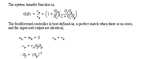
• The relevant transfer functions are,
• The feedback error controller can be selected to reduce the errors. The typical design technique is, to design for minimal error or disturbance.
• Develop the system transfer function (given before) for a command feed forward controller
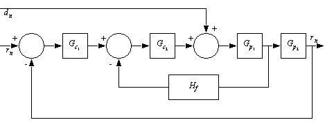
1.4.3 Cascade
• By adding extra feedback loops we can add levels of robustness to a control system.
• In this case the control loops appear to be nested.
• Consider a cascade control system for disturbances,
• Now consider a cascade controller for a multistage process, such as a sewage treatment plant with sequential tanks with varying flow rates. Here the disturbance would be the sewage flowing into the first tank. the two process blocks are the treatment tanks. The output is water returned to rivers The controllers vary the flow rates by looking at parameters for both tanks.
• To do design/analysis for these controllers we do an analysis of the innermost feedback loop. This then becomes a process, and we do design/analysis at the next higher loop.
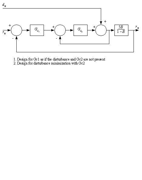
• Select controllers for the system pictured below,