• The most fundamental laws for doing circuits calculations are Kirchof’s current and voltage laws

• When doing (linear) circuit analysis there are three main areas,
- DC (Direct Current) - the simplest form of analysis.
- AC (Alternating Current) - the voltage and currents are continually changing.
- Transient - here we look at the specific changes in a circuit as voltages, etc. are changed.
• Most electrical circuits are assumed to be at rest initially, but this is not essential.
• When electrical circuits reach DC steady state (infinite time), capacitors act as if they are open circuits, and inductors act as if they are short circuits.
• Typical components in electrical circuits include,
• Recall that current is the flow of electrons (matter) and hence is conserved.
• We can also consider the power and energy in an electrical system

• Resistors are the simplest electrical element, and these are assumed to be perfectly linear.

• Resistors tend to dissipate energy in a system as heat.
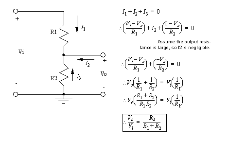
• One common application for resistors is as voltage dividers. This allows a voltage to be reduced, as a ratio of two resistance values. This technique is best used when there is no current drawn out.
• There are a variety of voltage and current sources. The simplest are chemical batteries.

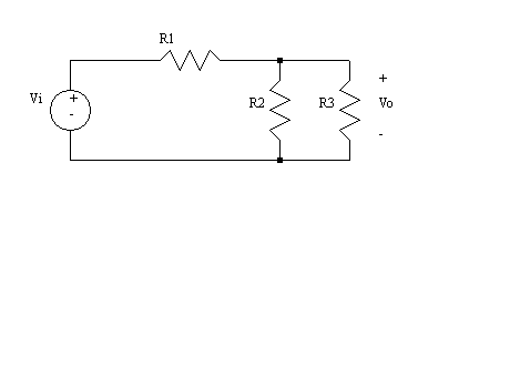
• These sources are assumed to generate a constant voltage or current. In truth the supply will weaken with age, or if excessive loads are drawn - this is very common with batteries.
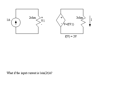
• We will also use dependent sources. These allow us to model some devices that would normally be difficult to work with. The voltage and current values are calculated using other values in the circuit.

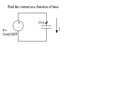
• Capacitors are two isolated metal plates very close together. We can force charge onto the plates, where it is stored. Hence, there is some capacity for storing electrons.
• Because of the electric field, when we change the voltage on a capacitor, it appears to allow a current to flow. But, in actuality when charge collects on one plate, it forces charge out of the other plate.

• When the voltage to a capacitor is not changing it will not allow any current flow. As a result we tend to call these devices DC blocking.
• Some capacitors (especially larger ones >1 uF) have a polarity. The symbols for these indicates the positive direction. If these are connected backwards, they will often explode (literally).
• Inductors are a necessary components in many circuits, but when possible we try to design these out. This is because they are large, prone to trouble (eg, wave a key near one) and costly.
• Inductors are typically made by wrapping a wire coil. This involves many turns (loops) and will often be given an inner core with a higher magnetic permeability.
• Inductors are the opposite of capacitors. The more current we pass through, the higher the voltage. As current flows a magnetic field is built, and when the current is removed the field collapses generating current.

• These devices tend to allow DC current to pass, but resist changing current. Hence these devices are often known as AC blocking.

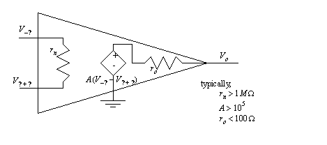
• Op-amps are not simple devices, but they can be made to act that way.
• Most inexpensive op-amps will handle frequencies up to 100KHz, and gains up to 100,000.
• They find good application for special functions such as,
- adders/subtractors/multipliers/dividers
• The basic calculation for an op-amp assumes that both inputs will be driven to the same voltage.

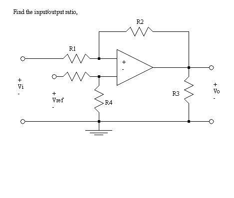
• The more complex op-amp model includes a dependent voltage source
