• Effects that can apply forces on a rigid body include,
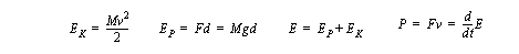
• We should also consider the energy and power transferred in translation. Keep in mind that energy is conserved. In real systems it doesn’t appear or disappear by itself.
• As we know well, gravity causes many objects to move.
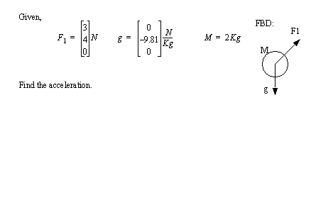
• We can model gravity as a simple force acting on the center of mass.
• The magnitude of the gravitational force is proportional to the mass of the object, and the direction of the force depends upon the location of the nearest large body. For us gravity is typically down, so we could write the gravitational force as,

• Note that the units balance out to provide forces in Newtons, or as accelerations.
• When we deal with other fields we can develop a force equation proportional to the appropriate effect. These might include,
- aerodynamic surface pressure
• NOTE: If the field is not uniformly applied to all of the mass, the resultant force will not go through the center of mass, and the result will be less force applied to pure translation, and the unbalanced forces will add to angular acceleration.
• If we sum the forces acting on a body, and set them equal to the inertial forces, we get a powerful set of equations capable of dealing with most cases of translation. This is called d’Alembert’s Law.

• Consider the simple example below,
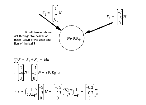
• We can also draw the inertia force on the free body diagram, acting on the center of mass. (Note: the inertial force is always opposite to the motion, therefore make it opposite to the direction of positive motion). In d’Alembert’s equation this is done by putting it after the equals sign.

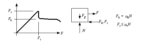
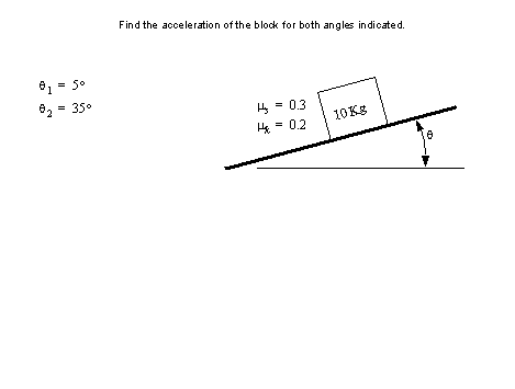
• Previously you have dealt with static (dry coulomb) friction. This applies when the body is not moving.
• When the body begins to move the nature of the friction changes.
• The simplest model of dynamic friction assumes a constant friction force. After the maximum static friction force is exceeded, the object begins to move, and the friction force drops to a lower value. Note that as the applied force ’F’ increases (hence velocity too) the friction force eventually diminishes. Therefore this model is good only at lower speeds.
• Friction dissipates energy from a system through heating, sound and vibration. The reduction of energy tends to make the system more stable.
• Springs are extremely common in most products.
• They usually take advantage of the Modulus of Elasticity (Young’s modulus) to produce a force proportional to deformation.
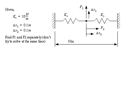
• For springs that undergo a simple elongation or compression, we can use a simple relationship - Hooke’s law.
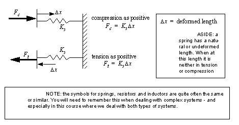
• Hooke’s law is valid for springs as long as thy are deforming elastically. Once they deform plastically they either fail, or the spring constant changes (usually becomes larger) and the undeformed length changes.
• Springs can be thought of as energy storage elements, much like capacitors and inductors.
• We typically assume that springs are massless. This allows us to ignore the transmission delay of forces along the spring (due to inertia). And, when we consider typical applications of springs this is almost always valid.
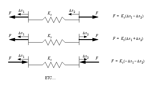
• Before the springs were shown with one end fixed. We will also have to deal with springs that have both ends moving. In this case we could rewrite Hooke’s Law based on the redefined directions.
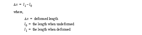
• ASIDE: a spring has a natural or undeformed length. When at this length it is neither in tension or compression
• Energy in a spring is the square of the deformation

• Friction is one technique for reducing energy in a system, and damping is another.
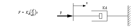
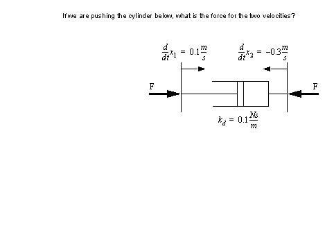
• Damping forces are actually proportional to the velocity rate - the faster you try to move them, the more they push back. The symbol below is for a ’dashpot’.
• These components are very popular in cars (and many other products) as shock absorbers.
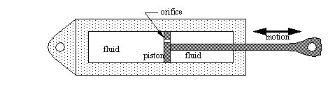
• Typically these devices are made using a cylinder with a viscous fluid. As the cylinder is move the fluid is forced to move between two chambers (ahead and behind the piston). To move between the chambers it must pass through a small orifice. The faster it moves though the more it fights back.
• To make the presence of viscous damping between two surfaces more clear, we can add a crosshatching between touching surfaces.

• Another effect that we often deal with is aerodynamic drag. The drag force increases as the square of velocity. The magnitude of the drag force coefficient ’D’ is approximated theoretically, or measured experimentally.

• The drag force coefficient is a function of,
- type of flow (laminar vs. turbulent)
• Cables are useful when transmitting tension forces.
• The centerline of the cable becomes the centerline for the force.
• If the force becomes compressive, the cable goes limp, and will not transmit force.
• A cable can be define a number of ways,
- length and angular direction
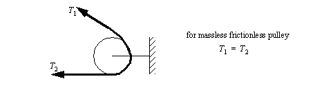
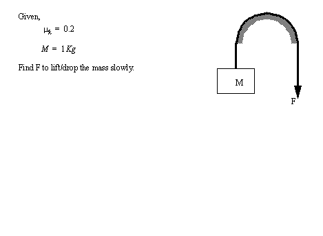
• Pulleys allow us to change the direction of a force acting through a cable.
• Typically we assume that a pulley is massless and frictionless (although we can assume both using material we will cover in rotation). If this is the case then the tension in the cable on both sides of the pulley is equal.
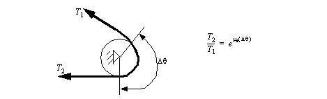
• We can also assume the pulley is fixed, and the cable must slide over the surface. This creates friction, and hence a resistive force.
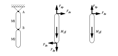
• Points of contact determine how separate rigid bodies interact.
• These points of contact will transmit action/reaction forces and moments between rigid bodies.
• When drawing FBDs for a system that has multiple rigid bodies, we must be careful to put the equal magnitude, opposite direction forces on joined rigid bodies.
• When looking at joints between rigid bodies, we should consider their degrees of freedom. Each degree of freedom will typically have a force or moment component equal to zero. If this is the case we can remove it from the free body diagrams.
• In 2D planar problems we can transmit up to two force components and one moment. Typical joints include,
• In 3D spatial problems, we can transmit up to three force components, and three moment components. Typical joints include,