• Basic process - Heat a thermoplastic material until it melts. Force it into a hollow (cooled) cavity under pressure to fill the mold. When cool remove the finished part.
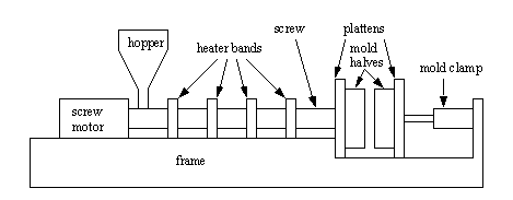
• A typical injection moulding machine is seen below with the covers removed. Plastic pellets are poured in the hopper, and finished parts emerge from the dies.
- a material hopper acts as an input buffer
- a heated chamber melts the material
- an injector forces the now viscous fluid into the mold
• Previous mechanisms used an injection plunger.
• Current mechanisms use a reciprocating screw,
- basically the screw extends from the hopper to the injection chamber.
- along the length of the screw chamber, heater bands are used to melt the plastic.
- as the screw turns, it moves raw solid plastic from the hopper, to the injection chamber. The buildup of pressure in the injection chamber forces the screw back until enough for a shot has accumulated.
- the screw is forced forward to inject the plastic into the mold.
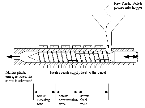
- there is a contribution to melting by pressure that allows the temperature of the heating bands to be lower.
- the purpose of the screw is to generate a homogenous melt with little orientation in flow direction.
• Typical zones can be identified on the screw,
- feed - a screw with large cavities to carry more material.
- compression - the depths of the screw thread reduce, leading to elevated pressures, and pressure induced melting.
- metering - small and uniform threads to provide controlled quantities. This also serves as a final mixing stage.
• Screws are often low/medium/high compression ratio as a result of the change of screw volume from the feed to the metering stages - screw selection will vary between materials, but a low compression ration screw will ensure good melting in most cases.
• Screws are nitride treated to improve tool life. Screws might also be made slightly smaller to compensate for thermal expansion when heated.
• Screws are often driven by electric or hydraulic motors.
• The heat capacity and melting point temperatures of various materials determine the energy required to melt the plastic and the energy to be removed for solidification (and for ejection).
• The volume of the injection chamber determines the maximum mold cavity size. The volume provided is often for polystyrene. When using other materials the volume can be corrected using the following formula. For example a 10 oz. shot,

• The mold is held closed with a certain clamp tonnage.
• As cycle times decrease, the plastic melt becomes less consistent.
• Each heating zone uses electrical heating bands with thermocouples, or pyrometers to control the temperature.
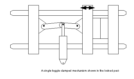
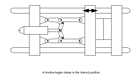
• When injecting, the mold is moved then clamped shut. The mold halves are mounted/clamped/screwed on two platens, one fixed, one moving. The stationary platen has a locating ring to allow positioning on the mold half over the injection nozzle. The moving half has ejector pins to knock out the finished part. Larger plates are found on larger injection molding machines.
• Injection molding machines pressure is calculated as injection pressure over an area in the mold. Consider the case where a mold with a 10 square inch mold is being filled in a 200 ton machine.

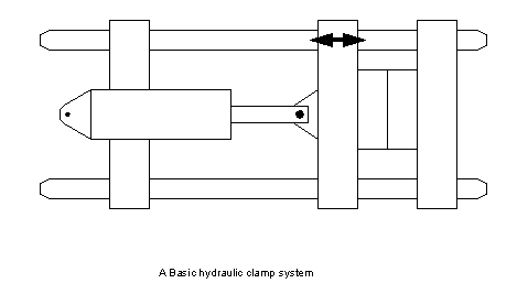
• The platens are actuated by hydraulic driven mechanisms. These are slow, but can exert great forces. In lighter presses other mechanisms can be used.
• A geared hydraulic pump is pictured below. Other types use vanes and pistons.
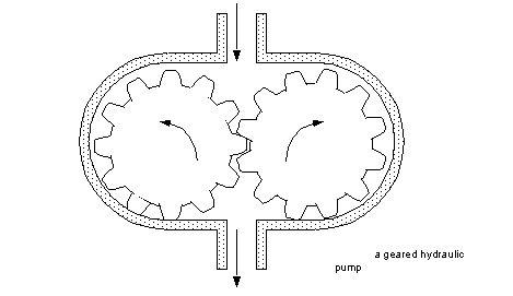
• Hydraulic systems use pumps to cause fluid flow. Resistance to that flow will allow pressure to build up. This fluid is directed through a systems with,
- relief valves to release fluid when a maximum pressure is passed
- a reservoir to collect uncompressed fluid
• The hydraulic system drives pistons and other hydraulic actuators.
• Injection molds are mainly made of steels and alloys steels. A simple mold is shown below.
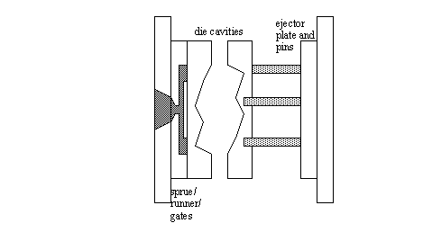
Locating ring - guides the injection nozzle into the mold.
Sprue Bushing - where the injected material enters the mold cavities.
Clamp front plate - Secures the front cavity, locating ring, and other components to the stationary platen.
Front cavity - holds half of the negative of the shape to be molded. Guide pin holes are put in this plate.
Rear cavity - the mating half for the front cavity that completes the negative of the final part. Guide pins are mounted on this to ensure correctly aligned cavities.
Spacer Blocks/Rails - used to separate the rear cavity from the rear clamp plate.
Ejector housing - contains the ejector pins to knock the parts out of the mold and forces the cavity back when the mold is closed.
Rear Clamp Plate - Supports the rear half of the mold on the moving platen, and provides rigidity under molding pressures.
• Components to consider in mold design,
• Factors that are often altered in the design are,
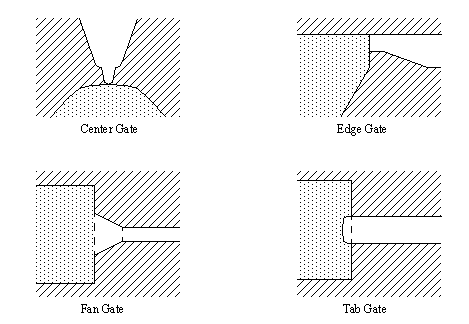
• Gating can be done a number of ways
• Runners carry the plastic to the injection gates and are often considered disposable or reusable. Typical runner systems are,
• Cooling systems allow rapid uniform cooling to increase cycle times, and reduce scrap. Typical techniques are,
• Ejection systems will push the part out of the mold when it is opened.
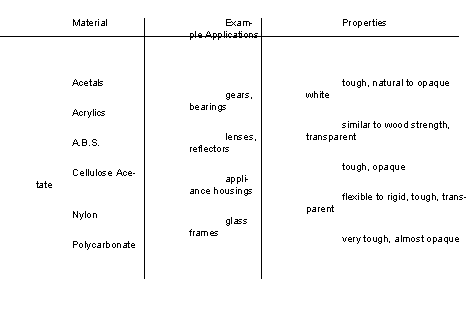
• Materials often come as raw beads. These can be mixed, colored, have other materials added, or reused.
• Quite often scrap parts are ground up, mixed with new materials and reused. But, caution is required to reduce contamination.
Barrel - the cylinder the injection screw sits in.
Cavity/Impression - The two or more hollow metal parts that contain the negative of the part.
Cold Flow - material that is too cool when injected will get a dull surface finish.
Core - a protruding (or male) mold component.
Crazing - a fine mesh of cracks.
Degating - separate parts from runners
Delamination - the surface peels off in layers
Dowels/Guidepins - used to mate mold cavities
Dwell - a delay time after filling the mold
Ejector Pins - push the part out of the mold as it is opened
Feed - the volume of plastic injected into the mold as it is advanced
Flash - a thin flat section that has “squirted” out of the mold
Gassing - trapped gas marks and burns the mold
Gates - the entry port between the runners and the parts
Granules - the pellet form that raw plastic is delivered in.
Granulation/Grinder - will reduce parts to granules for reuse
Inserts - parts placed in the mold before closure and injection. These become an embedded part of the final product
Nozzle - the plastic is ejected through the nozzle to the mold.
Polymers - The chemical category of plastics
Powder - a finely ground material
Preheating - plastic may be heated before use to remove moisture contaminants
Purging - a few purging shots are made when changing the material
Ram - opens and closes the platens
Regrind - reclaimed plastic granules
Release Agent/Spray - A spray, such as silicone, can be sprayed into tight molds to ease part removal.
Runners - connect the gate to the sprue
Safety gate - the gate must close and shut the operator out for the press to close.
Shot - one injection of plastic
Short shot - insufficient plastic is injected
Shrinkage - reduction in size as mold cools
Sinking - Surface deformation on parts.
Sprue - excess plastic between the injector nozzle and the mold
Vent - A small gap that allows air to escape as it is displaced by molten plastic
Warped - Cooling stresses cause a part to twist, or warp, to a new shape.