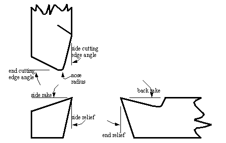
• A lathe toolbit is shown in the figure below, with a few terms defined.

• In general, as the rake angle increases (positive), the cutting forces are reduced, the surface finish improves, and tool life increases.
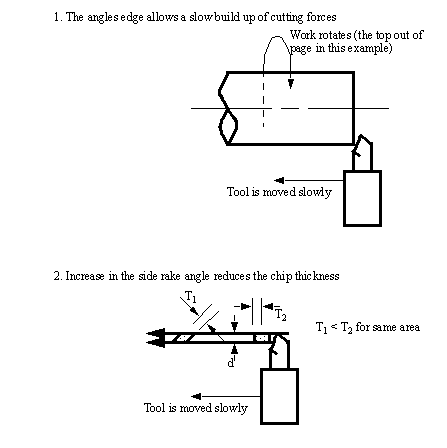
• The side edge cutting angle has two effects outlined below,
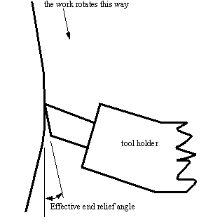
• The End Relief Angle prevents friction on the flank of the tool. The holder for the bit is often angled, and the end relief angle must be larger than the tool holder angle to prevent rubbing.
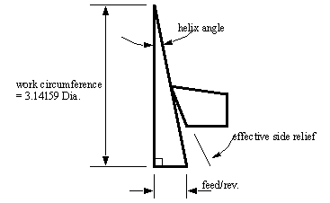
• The side relief angle has a function similar to the end relief, This angle must exceed the feed helix angle.
• Increasing the nose radius improves the surface finish. But this reaches a limit.
• Threads are cut using lathes by advancing the cutting tool quickly so that it cuts in a helical band. This helical band is actually a thread. The procedure calls for correct settings of the machine, and also that the helix be restarted at the same location each time.
1. The tool point must be ground so that it has the same angle as the thread to be cut. Typical angles are 60° for Vee threads, and 29° for ACME threads. A thread gauge can be used to measure thread angles. (also called Centre Gauge or Fish Tail Gauge).
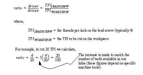
2. The correct gear ratio is required between the machine spindle to the lead screw. This can be determined with the equation,
3. The compound slide is set at half the thread angle. This is so that as multiple passes are made to cut the thread (most threads require a few passes to cut), the tool will be advanced in by the compound slide in such a way that only one face cuts. If both faces were used for cutting there would be a good chance of vibrations and chatter. For example, if a 60° thread is being cut, the compound rest is often set at 29°.
4. The cutting tool is set in the holder perpendicular to the work, and the fishtail gauge is used to check the angle of the point.
5. The In-feed is set to the surface of the part for the first pass (quite often the first pass just scratches the surface to allow visual checking of the settings). On each subsequent pass the infeed will be set closer.
6. The cross slide is set at the same location for each cutting pass. i.e., the dial setting is zero.
7. The In-feed is adjusted on the compound slide for each pass by moving it in a distance. A simple measure of this distance is,

************************** INCLUDE CHASING DIAL FIG 31-13
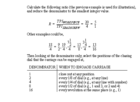
8. The chasing dial is used to restart the thread cutting in synchronization with what has been cut before. (If this step is not done properly, the notches in a thread might be cut over existing ridges - effectively cutting the entire thread flat to the bottom). The carriage of the lathe in driven across by a split nut. When the split nut is closed over the lead screw, it begins to move. It must be clamped over the lead screw when it is at the right angle. The method for doing this is with the chasing dial. The chasing dial has 16 different locations to engage at. In some cases you can engage the nut at any time, in other cases there are only a few positions to engage at. The basic rules are,
• Tapers can be cut with lathes quite easily.
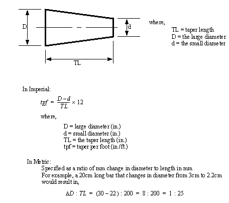
• The typical measures for tapers are shown below,
- Lathe-Spindle Nose - Used for alignment of hole/shaft pairs
- Self Holding Tapers - Used for stability
Taper shank drills, reamers, sleeves, etc.
• There are some common methods for turning tapers on a lathe,
- using a taper turning attachment
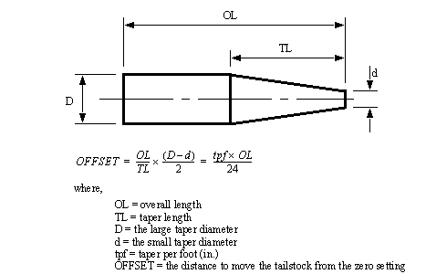
• Off-Set Tail Stock - In this method the normal rotating part of the lathe still drives the workpiece (mounted between centres), but the centre at the tailstock is offset towards/away from the cutting tool. Then, as the cutting tool passes over, the part is cut in a conical shape. The method for determining the offset distance is described below.
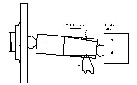

• The Compound Slide Method - The compound slide is set to travel at half of the taper angle. The tool is then fed across the work by hand, cutting the taper as it goes.
• Taper Turning Attachment - Additional equipment is attached at the rear of the lathe. The cross slide is disconnected from the cross feed nut. The cross slide is then connected to the attachment. As the carriage is engaged, and travels along the bed, the attachment will cause the cutter to move in/out to cut the taper.
• Form Tool - This type of tool is specifically designed for one cut, at a certain taper angle. The tool is plunged at one location, and never moved along the lathe slides.