jpf 1.1 Work Coordinates
Work coordinates are different coordinate systems within the working envelope of the machine. For instance if I have 3 work pieces clamped to the table, I may choose to run the same program in three different locations. Each location is identified by its own work coordinates.
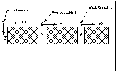
Figure 6. Top view of table showing locations of work coordinate systems 1, 2 and 3.
Work coordinates are measured from the machine's home position. The machine is in the home position when the spindle is raised to its highest position, the table is out toward the operator and the table is pushed to the right as much as possible. Work coordinates are entered into a data table of the machine controller. They do not appear in the part program. Instead the each set of work coordinates are referenced by a G code, G54 through G59 has been set aside for identifying work coordinates. G54 is traditionally used to show the machine coordinates. In other words the work coordinates stored in the G54 slot art the home coordinates of the machine. We will use G55 for our work coordinates.