• The purpose of drafting is to present technical ideas in precise and concise forms.
• A properly drafted drawing should be understood by any engineer.
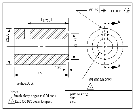
• A sample of a drafted drawing is given below.

• This is the use of drafting boards, pencils, pens, and a number of specialized tools for drafting. While this method is still very popular, the techniques used in manual drafting are quickly being displaced by CAD (Computer Aided Design) systems.
• I will not cover some of the manual drawing topics list below, but more information on them appears in a large number of drafting books.
• The problem with drafting is that the paper is flat, while the object drawn is not.
• To get around this we can develop a number of views to work with.
• This method of developing views is known as Orthographic projection
• This method eliminates the perspective distortion in real vision, thus making it easier for technical depiction.
• In this method, object faces that are parallel to the viewing plane are shown as actual size, but objects that are not parallel are foreshortened.
• The number of views used is a function of the geometry. For a simple object such as a washer, only one view is needed. A more complicated object, such as a piston, would require at least two views.
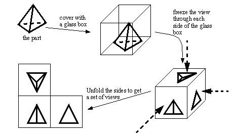
• The views are developed as if a glass box was placed over the object. The view from each direction was frozen, and when the box is unfolded, the resulting views are seen.
• Imaging the case below of a small tetrahedron (a three pointed triangle),
• The drawings are layed out with certain conventions. The example above is continued below for illustration, In the figure extra construction lines are added to show how the drawings in the different views are related.Note that the top view is related to the side view using a 45° line. These properties are a result of the ‘glass box’ concept. The folding lines are often shown on drawings (they have two dashes and one long). Also note that in the figure shown below, the points in the top view will be the same distance from the folding line as they are in the side view.
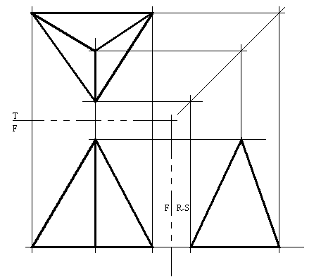
• The layout of the drawings is done by convention. In this drawing the right side view is to the right of the front view. If this drawing observed european standards, the right side view would be on the left hand side.
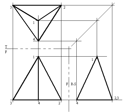
• A useful method for keeping the large number of points in a drawing sorted is to number them. For example,
• The view that is selected as the front is arbitrary, but it should
- be a natural front to the object.
• The number of lines on drawings will become confusing, therefore this calls for some method for differentiating between lines.
• Hidden lines are dashed lines used to show lines that not visible.
• Centre lines are used to show the axis of rotation for an object surface. These lines have long/short dashes.
• Construction lines are drawn on to help locate final drawing lines. These lines are so light that they are often not even erased when the drawing is complete.

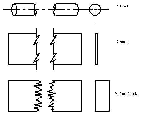
• Some objects have disproportionate dimensions. As a result, it may be necessary to ‘break’ them to show any reasonable level of detail. There are three types of breaks commonly used,
- S breaks - for round objects
- Z breaks - for thin long/wide objects
- freehand breaks - for long rectangular objects
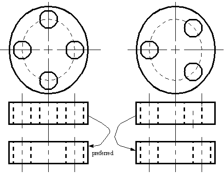
• Aligned features - in some cases, features are revolved, and shown at a consistent radial distance, but not necessarily in the correct position.
• Holes are commonly rotated to simplify views
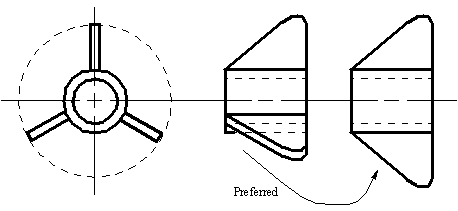
• Ribs and wings are commonly rotated to simplify views
• Large features on parts may be rotated to simplify views. small features, such as slots may also be rotated between views for clarity.
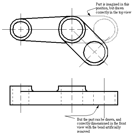
• Sheet metal parts start out flat, but are deformed to new useful shapes. Therefore it is common to draw sheet metal parts in the deformed, and the undeformed state.
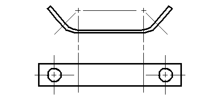
• Incomplete views - certain details can be omitted to simplify the view. This method produces drawings that are not correct, but they are commonly used in practice.
• Some views will end up having an excessive number of hidden lines. To combat this problem, we may sometimes just leave them out.
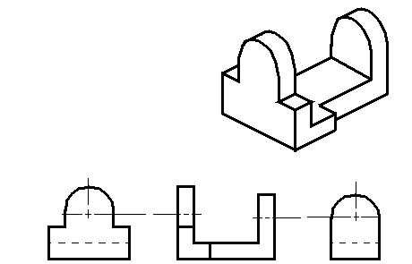
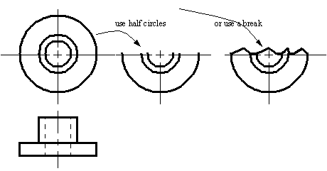
• Large radial/cylindrical parts are often cropped to save space. But, enough is shown to make the remainder of the geometry obvious.
• when there are complicated internal features, they may be hard to identify in normal views with hidden lines. A view with some of the part “cut away” can make the internal features very easy to see, these are called section views.
• In these views hidden lines are generally not used, except for clarity in some cases.
• The cutting plane for the section is,
- shown with thick black dashed lines.
- has arrows at the end of the line to indicate the view direction
- has letters placed beside the arrow heads. These will identify the section
- does not have to be a straight line
• sections can be lined to indicate,
- when the section plane slices through material
- two methods for representing materials. First, use 45° lines, and refer to material in title block. If there are multiple materials, lines at 30° and 60° may be used for example. Second, use a conventional set of fill lines to represent the different types of materials.
• Full sections - generally a straight section line cuts through a part to give a complete view of the inside. This section typically replaces one of the views that is confusing.
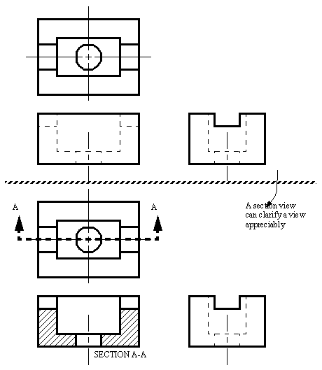
• Full sections will experience difficulties when the features do not lie along a single line.
• We can use a section line that is turned to cut through features. This view can be used to replace one of the principle views.
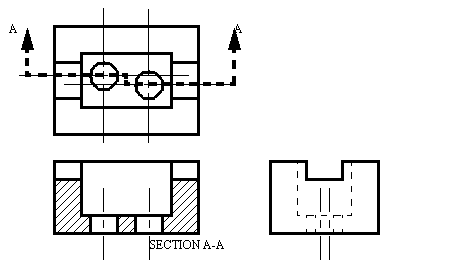
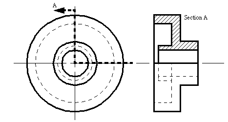
• In some cases it is better to illustrate internal features with both a section, and a full view. In this case we can cut away only part (a quarter) of the object, and draw a view that is half normal, half section.
• this method is well suited to symmetrical parts, with the section starting at the axis of symmetry
• Take note that the section line here only has one arrow head, but the direction must be observed
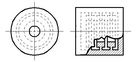
• Instead of doing large scale sections, we can cut away a very specific region of interest.
• In this case a break line is used, and the cutting plane lines used in other cases are not applicable.
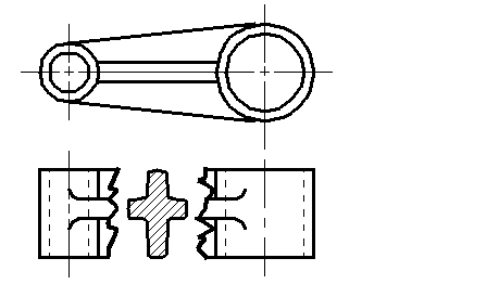
• When we have transition pieces, such as ribs, or airplane wings, we will want to show the shape, but this is not easy with conventional views, In this case we can break out a section.
1. select a characteristic section, and draw cut lines to either side.
2. in between the breaks, draw a section that is rotated 90° so that it is obvious on the drawing.
• This method is useful when space is at a premium
• The cutting plane line is not used with this technique
• this is a more exact alternative to the revolved section method.
• With this method a break is not used, but a cutting plane line is. The sections are then drawn at some other location on the page.
• The only features shown are the features of the section.
• labels such as A-A, B-B, etc are used to avoid ambiguity.
• these views are often placed at a distance and arranged in the same order as the sections.
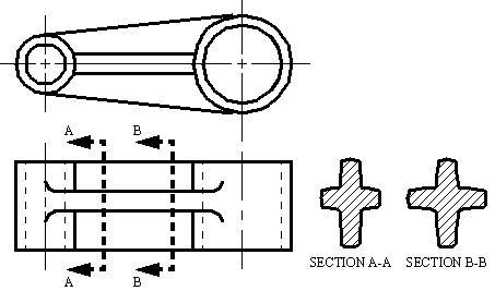
• These section may also be shown using lines extended from the object
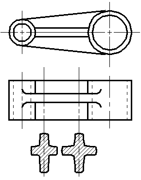
• modified scales may also be used with appropriate notation
• A section can be done that does not lie in one of the primary planes.
• This done as a normal section

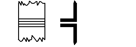
• This method is used for assemblies of thin materials, such as sheet metal.
• This illustrates how the pieces butt up against each other.
• The sections are filled with black, but a small space is left between the piece to indicate the assembled faces (operations such as crimping, spot welding, etc are used for these)
• When placing parts together we want to verify that they will match, and that they can be assembled. We also want to provide assistance to the assembler. To do this a cut away assembly drawing can be used.
• There are a number of elements present in these diagrams,
- a parts list with numbered items
- generally section views are used, and oriented along the main assembly axis
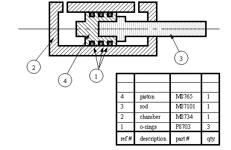
• Because sections are to clarify confusing features on diagrams, they are sometimes not theoretically correct.
• A few of the cases that are considered when working with sections are,
1. cutting lines may intersect ribs, but they may be drawn offset somewhat to clarify the rib geometry.
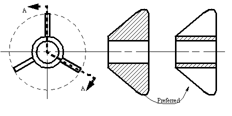
2. sections may be aligned to clarify the views
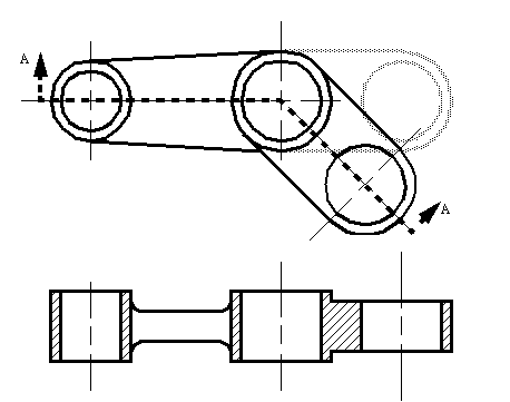
3. If a cutting plane cuts through intersecting features, the less important feature may be omitted for clarity, or to save time. For example, two rounds that intersect at an angle other than 90° would have an unusual shape, if one is not drawn, the section becomes much easier to do.
• The glass box can also be folded at odd angles. This technique produces views known as Auxiliary views.
• These views are useful when we want to draw a view of a surface that is not normal to one of the primary viewing planes.
• common terms used for this method are true size, and true shape. keep in mind that if a feature does not lie parallel to one of the primary viewing planes, it will appear distorted in every view.
• These views can be constructed from any view in a drawing. typical names for these identify the view that they are drawn from,
• We can also use auxiliary views to project other views for geometric purposes
• hidden lines are typically not used in auxiliary views, unless needed for clarity. Also, a number of surfaces are not included because they are distorted, and of little value.
• typically steps followed to construct an auxiliary view,
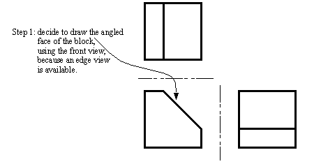
1. select the face that is to be drawn as i) a true surface, ii) a true length line, iii) an end view of a line.
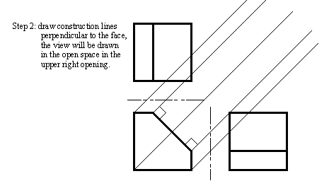
2. draw construction lines perpendicular to the surface/line/point of interest. This line should go in a direction, and far enough that leaves enough space for the view.
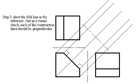
3. draw a folding line at an appropriate distance. This will act as a reference plane.
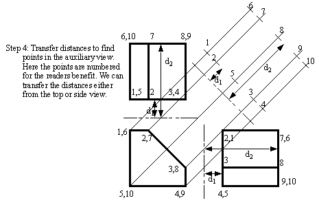
4. transfer distances from another view. This view will typically be the view adjoining the view that the auxiliary is drawn from.
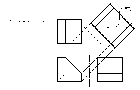
• an example is given below, and all faces are drawn for illustration, but normally only the angled face would be drawn. Because this is the first auxiliary from the drawing, it is called the primary auxiliary view.
• There are special drafting techniques for rounded, or curved surfaces, these can be found in any drafting textbook.
• sometimes it is necessary to make an auxiliary view, using an auxiliary view. When this is done, the first auxiliary is constructed as normal. The second auxiliary is made from the first, but the distances can only be transferred from the first auxiliary for the second auxiliary.
• These views can be needed for a number of purposes, but generally they will be needed when the object does not lie perpendicular, or parallel to any of the viewing planes.
• The use of drafting to determine geometric properties, such as shortest distances between points and lines.
• These methods can also be used to solve statics (vector) problems, etc.
• These methods use extensions to the methods of auxiliary views that allow curved surface to be considered.
• the basic steps in these methods are,
1. find the true lengths of a line
2. find the end view of a line
3. find the edge view of the surface
4. find the true shape of the surface
• These steps will allow determination of a number of properties,
- points can be projected into other views
- lines can be projected into other views
- the true length of a line can be determined
- a point view of a line can be found
- distances between points and lines can be found
- distances between lines can be found
• These views are done as a way of realistically drawing objects. This is not correct, as a perspective drawing would be, but it is very good for engineering problems.
• The viewing directions are skewed so that up is still up, but straight back now goes to the left and back, and right goes to the right and back. Both of the moved axis are drawn at 30° to the horizontal.
• The values measured off these views will be accurate when measured along the axis.
• There are a number of special techniques of interest when doing manual drafting, but of declining interest in view of modern CAD systems. A list of these techniques are given below, and are described in good detail in most drafting books,
- cavalier (45°, with full depth size)
- cabinet (0-90°, with half depth size)
- general (0-90°, with between half and full depth size)
