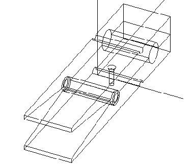
1.4 MULTI-DOMAIN PLANNINGIn both examples so far the process domain has been limited to machining. It is very unusual to find a part that is manufactured using one type of an industrial process, such as machining only. Therefore another important test of the planner was planning for a product with mixed operation types and parts. The part selected is shown below. The product is a paper clip in the form of a ‘clothes pin’. The clip has two halves and a connecting spring. On one of the sides there is an advertising logo embossed on. The same side also has a hole drilled into it so that the clip may be mounted on a wall. In total there are a number of possible technologies that may be applied to the part. First, the spring is quite straight forward, and only involves the forming of some wire. In the second case, either of the clip halves could be made by injection molding (this was used in the actual production of the sample product used). But, in other cases, it is possible to machine the entire part from a piece of polypropylene. The decision can be based on the quantities of parts to be produced. For example, to machine two halves of a clip for a prototype might only cost a few hundred dollars, as opposed to $50,000 to $100,000 for molds for injection molding (the figure are based on my personal experience). A graphical representation of the clip is shown below. 
// This file contains a test part for the BCAPP system. The part is a // large Plastic Clothes peg which is intended for use as an paper // holder. It is also has an embossed logo on the side. // -------------------- Main Geometry Definition --------------------- EQUATION: ( : Spring;attach_spring Logo_Side;position_logo_side // ------------------ Assembly and positioning information ---------- // -------------------- Defintion of Logo Side of Clip -------------- EQUATION: ( : ( & Clip_half ( ~ Screw_hole );position_screw_hole // description = ‘ add CBS logo ‘ // ---------- This is the box to put the pins into ------------------- description = #10_standard_box EQUATION: ( & OUTSIDE ( ~ INSIDE ) ) // ---------- This is the clip spring (This is a tough definition) --- // ------------ The geometry for one half of the clip is defined here EQUATION: ( & ( ~ B ) ( ~ C ) ( & A E ) ( ~ D ) ) Big Clothes Peg Product Description File (cont’d)// ------------------------------------------------------------------ Big Clothes Peg Product Description File (cont’d)After the rule file listed previously (in Figure 1 The General Rule File Developed for Discrete Manufacturing (cont’d)) was applied, the following output file was obtained. -------- Work Order Sheets ------------ OPERATION SUMMARY_SHEET: Clip_half_PART - Quantity 2.000000 ------------------------------------------ 0 cut a block from stock with hot wire OPERATION SUMMARY_SHEET: 0:Logo_Side_PART - Quantity 1.000000 ------------------------------------------ 1020 drill hole : COMBINED_SET_10 OPERATION SUMMARY_SHEET: Logo_Side_PART - Quantity 1.000000 ------------------------------------------ 2000 fixture part : LOGO_PART_18 OPERATION SUMMARY_SHEET: Spring_PART - Quantity 1.000000 ------------------------------------------ OPERATION SUMMARY_SHEET: Big_Clothes_Pin_PART - Quantity 1.000000 ------------------------------------------ 4000 fixture part : Spring_PART;attach_spring 4010 add part to fixtured part add Clip_half_PART to COMBINED_SET_28 4020 add part to fixtured part Operation Plan for the Big Clothes Pin (cont‘d)The plan above exhibits a few very important factors. First, the plan contains a range of operations, from forming to cutting. Thus showing the independence from a single processing domain. Also shown is the ability for the planner to break the product into natural components, one of these being the clip half with the logo added. In this case the planner separated out the addition of the logo, even though the design does not indicate it as an individual assembly. This is in keeping with what would happen in an industrial environment, where a number of clip halves would be made in a large economical batch, then the logos would be added a later time to smaller batches, as requested by a customer. The reader is also asked to consider the flexible nature of the description within the plan. This indicates that the plan can be easily customized to suit the varying needs and abilities of the manufacturer. |