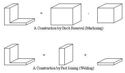
1.2 A SIMPLE MACHINED PARTMachined parts come from a very limited domain. When machining, most parts involve selecting a piece of stock, and then removing metal to get to a finished part shape. Generally there will be two ways a designer would approach this problem. The first would be when he selects a basic piece of stock, then subtracts volumes until the final part shape is reached. At present this approach is easily handled by the system. On the other hand, if the designer decides to build up a part from primitives, then a piece of stock must be identified for machining. Since stock identification requires geometrical reasoning, and this has not been added to the method yet, it is not possible to deal with this case for production. It has been stated in the past [Requicha and Vandenbrande, 1988] that the alternate representations are a problem. However, if we use the knowledge about what the alternate representations are, and what they mean, then it is possible to convert between them. There are two equivalent cases shown below in Figure 1.1 Alternate Representations for the Same Part. 
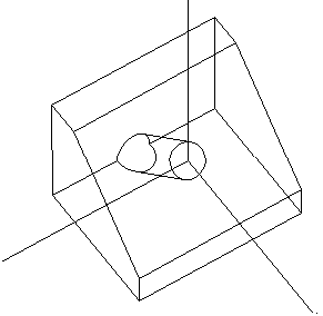
If a designer has chosen one representation or another it would suggest a particular process. In the top representation, the designer would obviously be suggesting machining. In the bottom, the designer would be suggesting some sort of joining process. At present BCAPP can plan for both of these processes, but until geometrical reasoning is added to allow transformation between the two representations, it will be difficult for BCAPP to suggest welding for the top part representations, and likewise machining for the bottom part. One of the first parts used for development is seen below. It is a block with an angles face cut off and a through hole drilled. 
The number of possible machining operations that can be used for this part is limited. In fact the number of reasonable CSG models for such a part are also limited. The design file for this part is given below. // An angles part for test purposes EQUATION: ( & BLOCK ( ~ HOLE ) WEDGE ) The part file only uses a single design equation to represent the design. As can be seen, I have constructed the basic form of the part with block and wedge primitives. While the basic form can be created a number of ways, the hole through the block can only rationally be made with a ‘( ~ CYLINDER )’ term, any other would be excessive, or redundant. When it comes to the formation of the block/wedge pair they exemplify the non-unique nature of CSG. This could be made by, - cutting a square block, and cutting off the parts where it doesn’t overlap the wedge, - cutting a wedge shape, and removing the sections where it doesn’t overlap the block shape, - cutting a square block, and removing the material on one half of a half-space plane, As mentioned before, there are two clear manipulations at work here. The first is simple equation manipulation, as in the commutation of the ‘WEDGE’ and ‘BLOCK’ above. In the second case, there is the selection of new equations and primitives, as in replacing the ‘WEDGE’ with the ‘HALFSPACE’. As mentioned before, only equation manipulation is used here. Therefore the discussion will centre about the first two cases listed above. Both of the cases above can be recognized with rules, and both are quite valid. But, it is not desirable to cut stock with a triangular cross section, as would be required in the first case. Recognizing this there are only a few rules for cutting stock in standard shapes, such as square and round. In addition to rules for recognizing stock, there are also rules for looking for certain shapes to cut externally, such as the wedge. It is known that this shape is external because it is ANDed with the stock. Whereas the cylinder is probably an internal feature because is in the form ‘( AND ..... ( NOT CLYINDER ) .... ‘. In simple terms the basic planning process will follow the steps below. 1. a) Setup equation ‘( & BLOCK ( ~ CYLINDER ) WEDGE )’ 2. a) Recognize the CYLINDER as a drill operation b) Add a drill operation to the process plan c) Alter the equation to remove the hole ‘( & BLOCK WEDGE )’ 3. a) Recognize the WEDGE as an external milling operation b) Add a milling operation to the process plan c) Alter the equation to remove the angled face ‘( & BLOCK )’ 4. a) Recognize the lone primitive as a stock selection b) Add a call for stock to the process plan c) Delete the last term in the equation to leave ‘NULL’ 5. a) Quit, because the ‘NULL’ equation means planning is done This plan is quite straight forward, and does get planned without problems. If the wedge and the block were reversed the plan would continue until it was time to get a triangular stock. No rule would be found for getting triangular stock, and the system would have to backtrack until it finds an alternative plan. Also of interest is the naive suggestions of machining volumes. When suggesting milling parts of the block outside the wedge shape, some geometrical calculations are required to determine the volumes to be milled. Geometrical information is not available, but if it was a CSG model of the volume as ‘( & BLOCK ( ~ WEDGE )’ would be the machined volume. The plan developed for this part is shown below. -------- Work Order Sheets ------------ OPERATION SUMMARY_SHEET: Block_with_Hole_PART - Quantity 1.000000 ------------------------------------------ 0 cut a block from stock with band saw This plan is the direct output from the operation planner, with detailed machining information not given. At the top we see that the Product name is identified. Second we see an operation summary sheet, that identifies the part, the quantity to be manufactured, and a number of operations. The first operation requires that stock be cut. Secondly, a milling operation is called for to eliminate the excess wedge. Finally, the hole is drilled. To be critical, there are a number of data details that would eventually have to be added to the rules to make them complete, such as a knowledge of available stocks sizes and shapes. Also important is that the call for milling naively calls for milling of a wedge shape. At its worst this would work, but it would be very inefficient. However, computer graphics tools could be used to show a picture of the part before and after for the benefit of human users. The final call for a drilled hole is fairly straight forward, and should work well. Detailed locations, etc. are not given here for most operations. This is for clarity, but the indication of block dimensions shows that the system is indeed capable of reflecting the detailed information. Another detail to point out is that it is possible that the drilling operation would be listed before the milling operation. This is not acceptable because both of the entrance faces for the hole would not be at a normal to the axis of drill insertion (i.e. the drill would slip). This sort of information requires some geometrical interpretation to allow rule conditions to be checked. This does not mean that future work cannot incorporate this feature, but it does mean in the present state some geometrically absurd operations will be suggested. |