Waldron, W., Farris, J., Jack, H., Pung, C., "Vertical Integration Project with Freshman and Junior Engineering Students", ASEE Annual Meeting, Pittsburgh, PA, June 2008.
Vertical integration project with freshman and junior engineering students
Freshman and junior engineering students participated in a final design project that was vertically integrated project during the Fall 2007 semester. Vertically integrated projects use teams that include students in the same discipline but different class years, e.g., freshman and junior engineering students. The projects were also horizontally integrated (students from different disciplines) since both Mechanical Engineering (ME) and Product Design and Manufacturing Engineering (PDM) students are required to take the junior class EGR 345 (Dynamic System Modeling and Control). The freshman students in EGR 101 (Introduction to Computer Design and Manufacturing) are also horizontally integrated because they have not formally selected their emphasis.
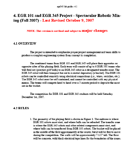
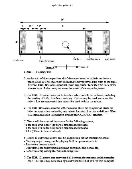
The project involved the design and build of robots to transfer ore (golf balls) from the mine to a container (bucket). The project was intended to emphasize project management and team skills to produce a complex engineering system from concept to completion. For each round, a combined team of freshman and juniors placed their robots on opposite sides of the playing field. Each team consisted of one junior team and eight to nine freshman teams but a maximum of six freshman teams could compete in a match. The freshman robots’ goal was to feed golf balls to their junior team's robot in a designated transfer zone. The juniors’ robot must then transport the balls to the bucket. The freshman robots could be controlled remotely using electrical connections, but the junior robot could not be controlled with any physical means.
Competitions1 and integrated projects2 have been assigned before and competitions like this have been held with freshman and junior students many times in the school using a tournament bracket. But each team is usually made up with either all freshman or all juniors. The novel aspect of this competition was that the junior teams had to develop partnerships and mentor their freshman teammates in order to be successful. For example, an outstanding junior team would not be successful if their freshman teams were unable to provide enough golf balls for the junior robot. Consequently, the juniors evaluated their freshman teams to decide which teams would compete. In some cases, less than six freshman teams were used to avoid getting in each others’ way. These relationships had seven weeks to develop and resulted in freshman robots that were significantly better than in previous competitions. The experience also helped the freshman see the challenges that lay ahead of them when they reach their junior year.
Experiences of Freshman Students
EGR 101 includes a lecture and a lab. All the work for the competition is done in the lab during the last seven weeks of the semester, but the lecture provides the foundation with topics on Engineering Graphics, gears, springs, pneumatic cylinders, electric motors, and calculations for machining parameters, e.g., spindle speeds, feed rates, and power requirements. The design process shown in Figure 1 was used for the final project and two smaller projects that were assigned earlier in the semester. The project was introduced to the students via a letter from Dr. Sirkus who is a fictional character who communicates with the students via Blackboard®. Dr. Sirkus is actually one or more instructors who respond to questions via the discussion board in Blackboard® about the rules and made decisions about materials and techniques that may or may not be used. This approach avoids the problem of having one instructor approve a student’s request when another instructor denies the same request, e.g., whether or not pneumatic cylinders may be used.
The final project began with the students being assigned to teams with two to three students. The teams were assigned based on the students’ previous work in the lab, and the best students (based on current lab grades) were put on the first team, the next best students on the next team, etc., until all the teams were assigned. This approach avoids the problem of strong students carrying most of the load while the weaker students coast.


Figure 1. Schematic of the design process.
During the first week of the project, each team was required to submit a list of design constraints based on the rules of the competition, evidence of benchmarking of at least 3 different systems, including a morphological matrix with three concepts for each function (see matrix in Table 1). Isometric hand sketches of three robots using a concept from each function were also required, where a given concept could be used a maximum of two times. Each team wrote a business letter to Dr. Sirkus summarizing their interest in the competition and progress so far.
Table 1. Morphological matrix.
|
|
Functions
|
|
Concepts
|
Move Robot
|
Transfer Ore
|
Release Mechanism
|
|
1.
|
Four wheels with dual gearbox
|
Rotating arm
|
Motor-driven lever
|
|
2.
|
Three wheels with dual gearbox
|
Rolling on rails
|
Trip wire
|
|
3.
|
Tank treads
|
Pneumatic cylinder
|
Contact with junior robot
|
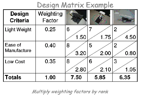
Figure 2. Decision matrix
Students made models of three of concepts using foam core, box cutters, and glue guns during the second week. Digital pictures, descriptions of each model, and a decision matrix for choosing the best concept were submitted along with solid models of each part of their design. A Decision matrix like the one shown in Figure 2 was used to select the best design. Process plans were required for the third week along with a Pro/E assembly file, G-codes to produce all parts with comments that identify which codes or lines were used to manufacture each feature of the part. A process plan was required for every part unless the part was purchased and no additional operations were necessary. For example, a process plan was required if a 6 ft piece of PVC pipe was purchased and then cut to 1 ft.
The process plans included the following items, and an example is shown in Figure 3.
The size of the stock material required to make the part. Three dimensions are required to specify the size.
The type of material required.
The machines used to manufacture the part.
Any fixturing required.
Any finishing operations required.
Process Plan
Part Name ___________ Part Number ____________
Stock Material and Size________________________
|
Op. #
|
Machine and file name
|
Work Holding Device
|
Part Location and Orientation(Sketch)
|
Tool (Size and Material)
|
Speeds and Feeds
|
Description of Operation
|
|
10
|
|
|
|
|
|
|
|
20
|
|
|
|
|
|
|
|
30
|
|
|
|
|
|
|
|
40
|
|
|
|
|
|
|
Figure 3. Process plan worksheet
For the fourth week, dimensioned and toleranced prints were required for all parts that were manufactured or modified. All parts (purchased and fabricated) were also due along with a Pro/E assembly file with a bill of materials (BOM) with index balloons. The assembled machines were evaluated in the fifth week and robots were tested and tweaked during the sixth week. A final report was due and presentations were given during the last week. The competition was held on the last Saturday before final exams.
Experiences of Junior Students
The catalog description for EGR 345 (Dynamic System Modeling and Control) shown below.
An introduction to mathematical modeling of mechanical, thermal, fluid, and electrical systems. Topics include equation formulation, Laplace transform methods, transfer functions, system response and stability, Fourier methods, frequency response, feed back control, control actions, block diagram, state variable formulation, and computer simulation. Emphasis mechanical systems.
After comparing the topics in EGR 101 and 345, it is clear that the capabilities of these two sets of students are quite different. EGR 101 is a first-year freshman course whereas EGR 345 is both very mathematical and applied. However, both the freshman and junior students were charged with some similar tasks. Both courses required the fabrication of robots that were capable of moving and transferring golf balls using motors, gears, and wheels. The difference was that the freshmen used switches to control their robots and the juniors used programs for autonomous control or wireless technology to control the robots.
Table 2 shows the mass and budget for the 1st place EGR 345 robot and Table 3 shows the mass and budget for their EGR 101 teams. Note that the total cost for the EGR 345 was around $220, but the costs for the EGR 101 teams were $18 to $33.
Table 2. Mass/budget for EGR 345 Team 1 (1st Place)
|
Description
|
Qty.
|
Unit Price
($)
|
Unit Weight (lbs)
|
Supplier
|
Price ($)
|
Mass (kg)
|
|
Micro Servo
|
1
|
18.00
|
0.016875
|
Cobble Stone
|
18.00
|
0.00767
|
|
Standard Servo
|
1
|
10.90
|
0.07
|
Acroname
|
10.90
|
0.03182
|
|
SingleLine Detector
|
1
|
14.95
|
0.2
|
Acroname
|
14.95
|
0.09091
|
|
Sharp Detectors
|
3
|
12.18
|
0.04
|
Digikey
|
36.54
|
0.05455
|
|
Wheels
|
2
|
3.50
|
0.05
|
Acroname
|
7.00
|
0.04545
|
|
Parallax Continuous Rotation Servo
|
2
|
13.00
|
0.125
|
Acroname
|
26.00
|
0.11364
|
|
1/8” Polycarbonate
|
-
|
-
|
-
|
Total Plastics
|
15.00
|
0.22727
|
|
Aluminum Angle
|
-
|
-
|
-
|
Ace Hardware
|
3.75
|
0.22727
|
|
Aluminum Screen
|
-
|
-
|
-
|
Ace Hardware
|
2.95
|
0.00568
|
|
Aluminum Stock
|
-
|
-
|
-
|
GVSU
|
2.56
|
0.10909
|
|
ATMega32
|
1
|
35.00
|
0.25
|
EMSYDE
|
35.00
|
0.03636
|
|
Printed Circuit Board
|
1
|
30.00
|
0.01
|
Sunstone Circuits:
PCB Express
|
30.00
|
0.00455
|
|
AA Batteries
|
4
|
0.50
|
0.055
|
Meijer
|
2.00
|
0.1
|
|
9V Battery
|
1
|
1.5
|
0.1
|
Meijer
|
1.50
|
0.04545
|
|
AA Battery Holder
|
1
|
1.79
|
0.05
|
Meijer
|
1.79
|
0.02273
|
|
LED's
|
3
|
1.485
|
Negligible
|
Radio Shack
|
4.46
|
0
|
|
Toggles
|
2
|
2.99
|
0.01
|
Radio Shack
|
5.98
|
0.00909
|
|
Wires, Fasteners, Misc.
|
-
|
-
|
-
|
-
|
-
|
0.0584
|
|
Total
|
|
|
|
|
218.37
|
1.1899
|
Table 3. Mass/budget for EGR 101 Teams (1st Place)
|
Team Names
|
Lab Section
|
Qty
|
Material
|
Total Cost ($)
|
Weight (grams)
|
Balls/min
|
|
Chris Simon
|
905
|
2
|
Wheels
|
$1.99
|
420
|
0
|
|
Tyler Schlientz
|
|
1
|
Dowel
|
$0.00
|
|
|
|
|
|
4"
|
PVC
|
$0.42
|
|
|
|
|
|
1
|
Tamiya 70168
Double Gearbox
|
$8.95
|
|
|
|
|
|
1
|
Tamiya 70093 3-Speed
Crank-Axel Gearbox
|
$6.50
|
|
|
|
|
|
1
|
Base (Scrap Plastic)
|
$0.00
|
|
|
|
|
|
1
|
Boom (Scrap Plastic)
|
$0.00
|
|
|
|
|
|
1"
|
Slider
|
$0.10
|
|
|
|
Total
|
|
|
|
$17.96
|
|
|
|
Ryan Bozio
|
901
|
1
|
Double Gearbox
|
$8.95
|
700
|
7.5
|
|
Andrew Cieslinski
|
|
1
|
3-Speed Crank
Axle Gearbox
|
$6.50
|
|
|
|
Justin Pattermann
|
|
2
|
Tires and Wheels
|
$5.50
|
|
|
|
|
|
1
|
Base (Plastic)
|
$0.50
|
|
|
|
|
|
1
|
Box (Plastic)
|
$0.25
|
|
|
|
|
|
15
|
Nuts
|
$3.00
|
|
|
|
|
|
1
|
Hinge and Screws
|
$2.11
|
|
|
|
|
|
1
|
Steel L-Bracket
and Separator
|
$0.25
|
|
|
|
|
|
1
|
Aluminum Support Rod
|
$1.18
|
|
|
|
Total
|
|
|
|
$28.24
|
|
|
|
Dan Sowa
|
905
|
1
|
Scrap Plastic
|
$0.00
|
465
|
9.5
|
|
Matt Dixon
|
|
1
|
Tamiya 70168
Double Gearbox
|
$5.95
|
|
|
|
Bretton Wainright
|
|
1
|
Tamiya 70093
3-Speed Gearbox
|
$4.50
|
|
|
|
|
|
2
|
Tamiya 70145
Tire Set
|
$7.25
|
|
|
|
|
|
2
|
Ball Caster
|
$5.00
|
|
|
|
|
|
1
|
Ladder-Chain
& Sprocket Set
|
$7.00
|
|
|
|
|
|
1
|
2 Part Epoxy
|
$0.00
|
|
|
|
|
|
1
|
Wire & Connectors
|
$0.00
|
|
|
|
Total
|
|
|
|
$29.70
|
|
|
Table 3. Mass/budget for EGR 101 Teams (1st Place) - continued
|
Phil Dial
|
901
|
1
|
Tire Set
|
$6.50
|
560
|
7.5
|
|
Scott Sarver
|
|
1
|
Gear Box
|
$8.95
|
|
|
|
Jacob Morris
|
|
1
|
2pk DPDT Switch
|
$1.49
|
|
|
|
|
|
1
|
1.5-3V DC Motor
|
$2.99
|
|
|
|
|
|
15"
|
0.25-20 Threaded Rod
|
$1.36
|
|
|
|
|
|
2
|
6-32 StoveBolt
|
$1.98
|
|
|
|
|
|
4
|
6-32 Nuts
|
$0.76
|
|
|
|
|
|
4
|
.25-20 Nuts
|
$0.80
|
|
|
|
|
|
8
|
.25-20 Washers
|
$1.20
|
|
|
|
|
|
1
|
Door Hinge
|
$1.99
|
|
|
|
|
|
36"
|
Fishing Line
|
$0.00
|
|
|
|
Total
|
|
|
|
$28.02
|
|
|
|
Derek Bross
|
901
|
2
|
Tires and Wheels
|
$6.00
|
315
|
7
|
|
Kevin Vermeer
|
|
1
|
Double Gearbox
|
$8.95
|
|
|
|
|
|
1
|
18" Aluminum Arrow
|
$1.50
|
|
|
|
|
|
1
|
Pipe Extension
|
$2.14
|
|
|
|
|
|
6
|
Screws
|
$0.98
|
|
|
|
|
|
6
|
Nuts
|
$0.98
|
|
|
|
Total
|
|
|
|
$20.55
|
|
|
|
Josh Bowen
|
901
|
2
|
Tamiya #70111 sports tire set
|
$5.85
|
880
|
7.5
|
|
Karl Kaluzny
|
|
1
|
Double Gear Box #70168
|
$8.95
|
|
|
|
Jordan Smith
|
|
1
|
3-speed crank-axle gearbox #70093
|
$6.50
|
|
|
|
|
|
1
|
Dowel
|
$0.25
|
|
|
|
|
|
6
|
¼’ Hex Nuts
|
$0.56
|
|
|
|
|
|
2
|
¼’ Carriage Bolts
|
$0.18
|
|
|
|
Total
|
|
|
|
$22.29
|
|
|
|
Brian Coté
|
901
|
1
|
Screws
|
$2.19
|
715
|
7.5
|
|
Tyler Devoogd
|
|
1
|
Bracket
|
$0.15
|
|
|
|
Ryan Mattox
|
|
1
|
Pulley
|
$0.90
|
|
|
|
|
|
1
|
Twin Motor Gear Box
|
$11.25
|
|
|
|
|
|
1
|
Single Gear Box
|
$8.50
|
|
|
|
|
|
1
|
Tire Set
|
$7.25
|
|
|
|
|
|
1
|
2" PVC Cup
|
$0.40
|
|
|
|
|
|
36"
|
Fishing Line
|
$0.10
|
|
|
|
|
|
1
|
Plastic
|
$2.00
|
|
|
|
|
|
12"
|
Wire
|
$0.25
|
|
|
|
Total
|
|
|
|
$32.99
|
|
|
|
|
|
|
|
|
|
|
|
Total
|
|
|
|
$179.75
|
4055
|
|
|
Average
|
|
|
|
|
|
6
|
Figures 4, 5, and 6 show the architecture and state diagrams and the wiring schematic, respectively for the 1st place EGR 345 robot. A picture of this robot on a scale is shown in Figure 7. As described in the rules of the competition in Appendix A, teams received one bonus points for each 100 g under 4 kg and each $10 under $300 for all equipment (EGR 345 and 101 teams) combined. Figures 7 - 11 show five of the six EGR 345 robots and Figure 12 shows the competition field.

Figure 4. Architecture diagram
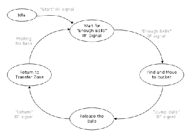
Figure 5. State diagram
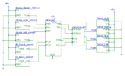
Figure 6. Wiring schematic
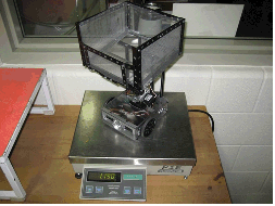
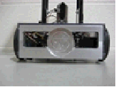
Figure 7. EGR 345 robot on scale and wireless controller - Team #1 (1st place)
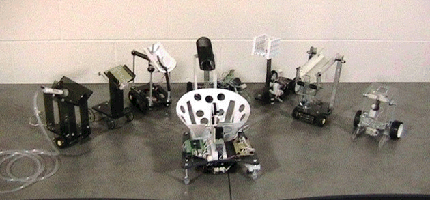
Figure 8. EGR 345 robot with EGR 101 robots - Team #2 (2nd Place)
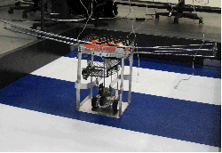
Figure 9. EGR 345 robot - Team #3
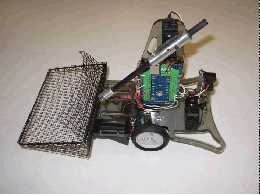
Figure 10. EGR 345 robot - Team #4
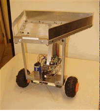
Figure 11. EGR 345 robot - Team #6
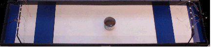
Figure 12. Competition field
Competition Results
The winning team described the results in the following way. “In the culminating event for this project, robot teams battled head to head in a single elimination tournament. The result of this was Team 1 winning overall, with a high score of 86 points, scored solely on the basis of the number of balls in the bucket.” See Figure 13 below.

Figure 13. Tournament bracket
Discussion
Partnering freshman teams with a team of juniors worked well for the most part. There were some logistical issues, but the juniors made an effort to schedule meetings that were convenient and they also visited the freshman labs to discuss design, manufacturing, and competition strategies. The rules were rather brief and there was a lot of discussion about the proper interpretation of the rules. Dr. Sirkus responded to over 120 questions, and there would have been many repeat questions without the Blackboard® discussion board.
The designs and fabrication by the freshmen continue to improve each year, but the quality of this semester’s projects were very good. It is likely that the mentoring of the freshmen by the juniors had a lot to do with the performance of the freshmen. The juniors’ experience and familiarity with more complex project work helped them provide direction for the EGR 101 teams. Teams 1 and 2 were significantly better than the other four teams because they used real time, i.e., wireless control. The autonomously controlled robots took much longer to collect golf balls from their freshman teams and to deposit them in the bucket. This lead to frustration for some freshmen because their grade depended on the success of their team. These students felt that their grade should have depended on the how well they transferred the golf balls to their EGR 345 robot and not how well their junior team performed. This may be one disadvantage to the partnering approach to these competitions, but it was outweighed by the experience of working with juniors and learning to work as a team with people with better or different skills. In the future, alternative grading rubrics may be used to address this issue. It was also a good experience learning first hand that just like in sports, a business or engineering team wins as a team or loses as a team.
Survey
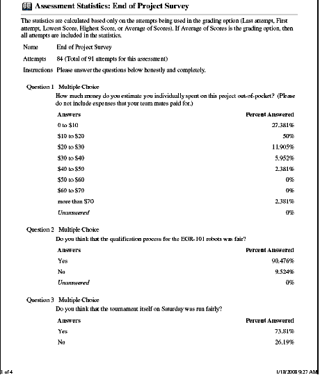
The end-of semester survey for the EGR 101 students is shown in Appendix B. The questions are paraphrased in the paragraph and the results are summarized in parentheses.
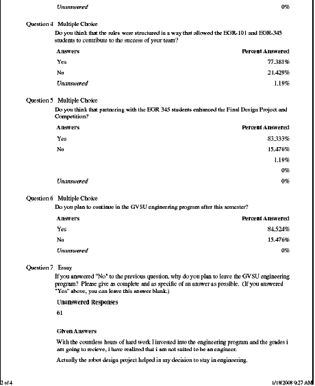
The survey asked questions about how much each freshmen spent of their own money on the project (most spent less than $30), was the qualification process fair 90% said yes), was the tournament fair (74% said yes), did the rules allow both freshmen and juniors to contribute 77% said yes), did you like partnering with the juniors (83% said yes), do you plan to continue in the engineering program (85% said yes), and if not why (most students leaving the program didn’t like the work, workload or rigor of the course(s)? An attrition of 15% is significant, but in recent years it has been decreasing as the university attracts stronger students.
Conclusion
Freshman students worked along side juniors in a seven-week project that included benchmarking, brainstorming, concept development, prototyping, solid modeling, CNC machining, machine testing, and a final competition. Each of the six junior teams mentored eight to nine freshman teams, and the result was a significant transfer of knowledge and skills for the freshman. The juniors also had the opportunity to sharpen their leadership skills because they had to manage their freshman teams to be successful in the final project.
These activities can be considered multidisciplinary because both Mechanical and Product Design and Manufacturing Engineering students are required to take the junior course. The project also includes vertical integration with freshmen and junior students. Horizontal integration was also involved since the freshmen course included students pursuing degrees in Computer, Mechanical, Electrical and Product Design and Manufacturing Engineering.
Overall the final project was a success and resulted in some quality design and builds, although there were some winners and not so happy losers in the final competition.
References
J. Oliva and W.K. Waldron Jr., “Virtual Design Competitions in a Computer Aided Engineering Course,” Proceedings of 2004 ASEE/NCS Conference, Western Michigan University, Kalamazoo, Michigan (2004).
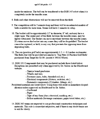
W. Waldron, P. Chaphalkar, S. Choudhuri, J. Farris, “Teaching Design and Manufacture of Mechanical Systems,” 2007 ASEE National Conference and Exposition, Honolulu, Hawaii, June 24-27, 2007.APPENDIX A - Contest Rules - Fall 2007
APPENDIX B - End of semester survey - Fall 2007