Appendix - Abbreviated Time-Line For Course
Pre-August - Notes entered into computer.
Aug., 12 - Notebook computer arrives.
Aug.,13 - Notes handed to printer.
Aug.,20 - Investigate computer projection equipment in assigned classrooms, the overhead projectors are only for TV, but there are 10baseT network sockets in rooms. There are data projectors in a locked hallway cabinet. Keys for cabinet are ordered.
Aug., 23 - Start up software to test run, it. Results are OK.
Aug., 26 - Classes start. The keys are not ready yet, I need to arrive early to ask somebody to unlock the closet. I test data projector, it only displays 640x480. The setup time was under five minutes. The last ten minutes of first lecture done with computer and data projector. When the lights are turned out the room is too dark to see paper (no side scatter of light as with overhead). The lights only go on in half of room. The trackpoint on the computer is very awkward to control scroll bars, etc. Even though part of the screen is chopped, it is mainly scrollbars. Using the word processor software, only half a printed page appears, and page breaks can fill a screen. The second section had windows with screens, and the light levels were fine. - Lesson Learned: do an early test run before the first lecture.
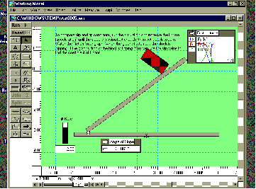
Aug.,28 - Arrived ten minutes early to get cabinet unlocked and equipment set up. In the dark room I decided to use overhead projector pointed at wall for ambient light - seems to work well, but proper lighting would be better. Took a regular mouse (instead of trackpoint) to help control problems. Used working model to run a simulation, seemed to clarify conceptual difference between statics and dynamics.
Aug., 30 - Settled on 10 minutes early as the expected pre-class preparation time. Noticed dark made some students sleepy. Ran entire lecture in dark, including questions. In second section I tried to do problems on board to parallel what was on the computer, had to remove fluorescent bulbs at front of room to get reasonable lighting. Show-of-hands survey indicated that; they liked not having to copy down notes - more time to think, no problems seeing screen, or following along. Projector cabinet key arrives today. - Lesson Learned: Be aware that the dark room puts students to sleep.
Sept., 4 - Arrived a bit late, having to pick up the data projector cost lecture time. Students seemed a bit sluggish in dark, tried turning on lights to solve a problem on the board, this seemed to help a bit. - Lesson Learned: Change the mode of presentation to keep them active.
Sept., 6 - The bulk of books, computer, etc. is somewhat annoying - needed to take the power supply because of the extended time (3 hours) of continuous lectures.
Sept., 9 - The notebook power manager was shutting down the laptop every couple of minutes, went to lecture on blackboard. Took power supply to second lecture.
Sept., 13 - Power manager acted up in first class, PC was almost unusable - Lesson Learned: decided to take power supply each time after, or disable power manager software. Picked up digital camera Apple Quicktake 100 - the camera was relatively easy to setup and use, but battery life was too short (<5 minutes) so the power supply was needed when downloading to computer. The camera took 8 or 32 pictures. The lower resolution of 320x240 was too poor for sharp detail, so the camera could really only hold 8 pictures.
Sept., 16 - Web Site almost ready.
Sept., 17 - Introduced students to Web pages, reception was good. Worked on getting web pages up, including hypertext links to gifs. This was only possible by tricking WebWorks into passing it through without converting characters. Lesson Learned: plan for the document conversion process, the software available still limits abilities. Made some graphics to go with pages - gives the pages a polished look. Took pictures with digital camera - it was very sensitive to light levels, and distance/close detail was blurry.
Sept., 18 - Presented in class using Netscape off local disk files - increased font sizes, and DPI for gifs (up to 120 from 74) to better fill screen. The text was more viewable on screen. By contrast the normal screen font is too small. Lesson Learned: Use Netscape instead of Framemaker to present.
Sept., 20 - Presented with netscape again, this time using the network and the Web site - this ran well, but as the morning progressed the transfer rates slowed, especially as the hour approached.
Sept., 23 - Presented off local disk again, ran much faster. Added course info to web site, including sample problems and syllabus. Prepared first midterm, and had answers prepared, and ready to post after test.
Sept.,24 - Got camera and started taking more pictures. Got copies of Working Model quick start guide, plan to give to students tomorrow, and will suggest a problem to try next week.
Sept., 25 - Demonstrated Working model in class by building a ball between wedges, a robot, and a block hung by two cables. Also gave out tutorial manual, and indicated that next week some problems will be assigned to be done on working model. Student reaction was ‘WOW’. Lesson Learned: Visual impact should be used whenever possible.
Sept., 26 - Fixing up things, but realize that pictures collected in future must be to fulfill need. there are too many pictures to take, and not enough disk space. Got some email questions about textbook problems. Did not have textbook. It would have been nice if all questions were on-line for easy reference, and so that notes could be added to the problems.
Sept., 27 - Exam day. Showed mpeg movie of Tacoma Narrows bridge - a good visual part. More videos would be great. Solutions posted on line, and students seemed to have them printed shortly after the exam. Lesson Learned: When possible post exam solutions on-line.
Sept., 29 - Some Working Model examples created for classes this week. Misalignment was a small problem - but more practice expected to reduce problems. A 3D problem is not possible using the current version.
Sept., 30 - Presented in class using Netscape only. This included working model links, and photographs. The models were Static, and a loss of interest was apparent. First working model assignment discussed as bonus. Student interest picks up. The lab version is not working well, (it later turns out that some computer labs don’t support the package) I load a copy of the demo software to my website for local download. Find transcription error in the exam solution posted on-line, fix problem on-line and mention to students. Lesson Learned: Even though we can change things on line, if it is printed mistakes are permanent.
Oct., 4 - The network locked up, had to present using framemaker - considered keeping copy of course on hard drive. Lesson Learned: The Internet is not reliable, have alternate solutions. SVGA to NTSC converter arrived - tried in class, very poor with high resolution graphics. Went back to data projector. Other problems, cables too short, and s-video connector only on ceiling mounted projector. Good rule of thumb, count on a loss of 50% of resolution, and avoid thin lines.
Oct., 7 - tried using the SVGA converter in class again, very poor appearance, but as okay with larger fonts, but the unit seemed to shut down after a few minutes.
Oct., 11 - Had classes, and then working model contest at the end. This seems to have set a fire in some students. Most were impressed. In general the interest level was higher in the smaller class. One very good technique with the data projector is too project the image onto a whiteboard and draw over the image using markers. This allows the students to add/refer to their notes.
Oct., 18 - A very effective use of working model to show the students slip/tip case for a block, and then calculate to verify.
Oct., 22 - Tried a test of SVGA to TV converter in class with large fonts. The students seemed to be happy with presentation styles, and agreed to an in class trial. Helvetica font seemed to be perceived as slightly better, by show of hands. Took a while and changed some of the notes to helvetica, and posted to net. Put some problem solutions on the net that were missing in the text.
Oct., 23 - Went to present in class with SVGA to TV and the network was misbehaving, so could not connect to site. The network was down today, so the students could not get access to the web pages, and I could not update.
Oct., 25 - Data projector did not work in first class, used the board instead. In second class found that the data projector was set for the wrong input. Lesson Learned: Even when the equipment works well, figure out why it is working well just in case. In the conversion process the multiplication sign was changed to a ‘yen’ sign. I also noted that in printing some of the equations were not printed properly, but the students were able to copy off the screen (or could use the web pages).
Oct., 28 - Data projector stopped working, and sent to get repaired.presented on board in class.
Oct., 29 - Presented in morning class using SVGA to TV converter. Did not seem to cause many problems.
Oct., 30 - Exam day. Did not have time to put exam solutions on net.
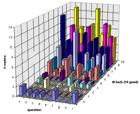
Nov., 1 - Returned exams - solutions not yet on net, but meeting students face to face to return papers (one at a time). Did the first survey in class. Used the SVGA to TV converter to present, the second class was seeing it for the first time, and complained of the poor quality.
Nov., 4 - Presented in class as normal using board mainly. projector is still missing.
Nov., 5 - Computer did not work.
Nov., 6 - Data projector did not work again. Will use computer and projector next class.
Nov., 8 - Data projector fixed, lecture proceeded as normal.
ADDITIVE MILLED POCKET MANUFACTURING
Hugh Jack, Assistant Professor, The Department of Mechanical Engineering, Ryerson Polytechnic University
ABSTRACT
Rapid Prototyping describes a category of techniques well suited to quick construction of newly designed parts. Typically in additive processes the parts are built bottom-up by adding subsequent thin layers that are essentially stacked cross sections of the part. This process is still less than a decade old, but already it is finding applications that make it economical. One the other hand the subtractive processes, such as milling are well established and understood. The trend to date has been for prototyping methods to focus on only one of the two philosophies. This paper describes a method that uses both additive and subtractive approaches. The parts are made using thick layers of a support matrix, such as wax, to support the work. NC milling techniques are used to cut pockets into the matrix. These pockets then act as moulds for a poured polymer. The successive addition of layers leads to very fast and flexible part manufacturing.
1.0 INTRODUCTION
Rapid prototyping processes (also known as free form fabrication) have become popular topics in manufacturing. Although these methods are not replacements for traditional manufacturing techniques, they fill a well identified need for production of prototype parts and tooling. In summary we can describe the processes as techniques to turn a computer based design file into a physical geometry within hours or days. An example of a useful application is that an injection mould die can be designed and produced using a stereolithography machine. The polymer based part can then be given a spray metal coating and used to turn out a few sample injection moulded parts, or investment casting wax cores [4]. The time frame for the parts might be months when done traditionally, but can be days when done with rapid prototyping. (All of the processes described in this section without references are commercial systems and further descriptions and references can be found in [1]).
The processes currently in use can be dichotomized as subtractive and additive[1]. The subtractive processes begin with stock material larger than the final shape of the part. Through material removal steps, such as machining, the stock is eventually reduced to the desired geometry. The additive processes start with nothing, and selectively add new materials to a base piece, eventually resulting in a complex geometry. Generally the additive processes have a number of similarities. Material is generally added in layers between .001” to .020” thick. These materials may be solid, and are cut, or are liquid/powder and are hardened. The layers are built up over some period of time until the part is complete. Some of the problems that face these techniques are that the parts require some form of support, and the materials that can be cut/hardened limit the types of materials available.
1.1 Additive Processes
The best known of the additive processes is stereolithography (STL). This process was initially introduced in the late 1980s and to date has resulted in a number of commercial machines. The process basically uses a vat of photopolymer with an elevated platform. A laser is swept across the surface platform using a raster pattern to selectively harden parts of the resin. The platform is then dropped, and the part in now covered by a new layer of uncured resin. This cycle continues until all of the part layers have been hardened. The mostly solid part is then removed from the bath, and placed in an intense light oven to cure any uncured resin. One of the difficulties with STL is that the resin bath does not provide proper support for certain parts with narrow bases, thin sections, or surfaces with no under support.
An answer to the support problems of STL was Solid Ground Curing (SGC). This process still uses the photopolymers, but in this case they are cured with a UV light that has been masked. The basic process has two cycles, one cycle produces masks for each layer, the second cycle uses the masks to produce the layers. The masks are produced using a process similar to photocopying, a black powder covers areas on a glass plate that are not solid on the part slice. In the second cycle the process first involves putting down a thin layer of photopolymer. This is then exposed under the mask to selectively harden resin. Any uncured resin is then removed, and replaced by wax. The combined layer of wax and polymer is then machined flat for accuracy. As these steps continue the part is built up inside a volume of wax, and when the part is completed the wax is melted away. This method seems to be preferred by those that can afford it.
Both STL and SGC are both criticised for their limited range of materials. Other competitors use creative solutions to allow more practical materials. For example Selective Laser Sintering (SLS) uses fine powders in a vat. The powders are spread in thin layers and a laser is directed over the surface. The chamber is kept at a high temperature, and the laser elevates the material temperature enough to sinter the powders. Layers are added until the part is done, then the loose powder is removed to reveal the final part. This process is still not capable of using engineering alloys, but will work with materials such as ABS [3]. Another similar technology is called Direct Shell Production Casting (DSPC). This method uses a vat of powder where loose powder layers in layers is selectively hardened using small jets of adhesive. This method has been used to successfully produce casting moulds. The powder based methods also face a number of problems with adhesives, powder packing, and material selection.
Three different types of processes use molten materials that are deposited by moving heads. Fused Deposition Modelling (FDM) uses thin filaments of thermoplastics that are fed into a heated head that moves on an apparatus best described as a 3D plotter. The melted thermoplastic is then wiped onto the part below. This method has a great deal of potential, but is obviously best suited for thin walled parts. A similar method has been used called 3D welding in which a metal bead is welded onto a supporting structure. Ballistic Particle Manufacturing (BPM) uses heated particles sprayed on a surface through a mask. As layers are sprayed through successive masks the layers of the part are formed. This technique can produce metal parts, but is hindered by the need for a large number of masks. Finally the sanders prototype uses a “print head” much like those found in ink jet printers. These heads dispense two types of materials that are both thermoplastics, but with different melting temperatures, or sensitive to different type of solvents. The head is moved through the workspace to deposit composite layers of both materials. When the part is completed the outer materials is removed. This method is well suited to finely detailed work.
Finally there are a set of processes that add preformed layers of materials such as plastics and papers. In Laminate Object Modelling (LOM) the materials are stored on large rolls of bulk material. The new material is rolled over the work elevator. A heated roller fuses the new layer on by melting an adhesive between the new layer and the existing part. A laser is then used to cut a pattern on the new layer. This pattern includes the outline of the work, and a hatching pattern to allow support material about the work to be removed at the end of processing. Another process uses layers of materials, such as green ceramics, that are cut separately, and then stacked on previous layers [2].
While all of these technologies are very exciting to watch and use, there are a number of inherent problems that generally arise. The use of laser light in a process generally results in higher equipment costs for the laser, optics, targeting, and focusing systems (machines cost $50,000 to $500,000 U.S.). The use of the laser, and other techniques also tends to limit the accuracy (typical values are > 0.002”). Material costs are high in some cases, such as the photopolymers (e.g. > $100 per litre). Thin layers result in a large number of layers for large parts and a proportionally high build time. The use of thin flat layers also results in a staircase effect on bottom/top rounds. Most of the techniques tend to be limited to smaller volumes by the complicated optics systems. Despite many manufacturers claims, many of the systems require high levels of technical knowledge from the operators. Material properties in many cases are limited to relatively uncommon materials. Finally, in many cases the supports required while building the parts can be difficult to plan and remove after the part is completed.
1.2 Subtractive Processes
The subtractive processes are a common and well understood part of manufacturing, and thus will only be discussed briefly. Basically, simple machining processes use a cutting edge to shear metal chips from a base piece. When done with care this can result in a high quality part with a desired geometry and surface finish. These methods work with most popular engineering methods, but often require some skill in fixturing the work, and selecting operation sequences. Some of the processes used are milling, drilling, turning, sawing, etc. Other more modern processes include techniques such as Electro Discharge Machining (EDM) where an electrode is brought near a surface, and a potential is applied, causing arcs that dissolve small quantities of surface material.
In general the methods for subtractive processes are well understood, and well developed. Typical workspaces for these machine can be as large as a house, accurate to much less than 0.001”, and easily controlled by a machinist using inexpensive commercial software. The disadvantages for these processes tend to be fixturing and selection of process parameters.
1.3 Hybrid Processes
Both the additive and subtractive processes are attractive for varied reasons. The additive processes have great potential for hands-off free form production of very complicated parts. But to get these advantages they have basically ignored many of the subtractive processes. It is the purpose of this paper to describe a method that combines a combination of both of these philosophies. In effect by getting away from thin layers, and a limited range of materials it is possible to decrease build time, and allow the use of precision machining practices.
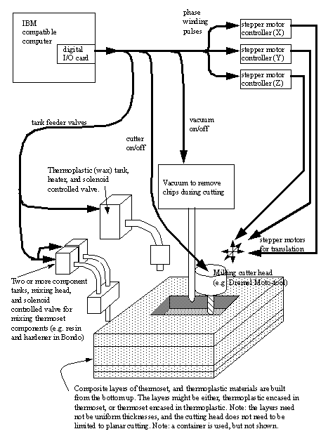
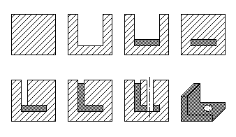
2.0 GENERAL OVERVIEW OF THE AMP PROCESS
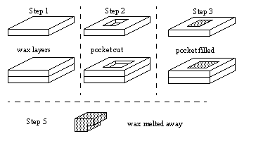
The basic steps of the process are shown in Figure 1. To produce this part in a practical setup, a container (metal to increase heat conductivity) would be filled with a layer of wax (a thermoplastic) somewhat thicker than the first layer, say half an inch. After this has cooled the wax is cut using standard NC milling techniques. Care is taken to vacuum up the chips so that the cavity is free of debris, and so that the chips may be recycled later to recover the wax. The pocket in the wax is now filled with a thermoset polymer. This sets and when hardened the top of the wax and the polymer are cut even, this maintains accuracy. Another layer of wax is added, and the process continues as before. When done the part will be encased in a block of wax. Placing the part in a hot wax or water bath will melt and remove the wax, to free the completed part.
Figure 1 - A basic outline of the AMP process
This technique will allow parts to be cut in very thick layers to increase speed. The wax matrix adds support to the part while cutting is being done.
2.1 Equipment
To date this method has been tried on a number of different experimental platforms. The original testing was done on a drill press with a milling tool in the chuck. This produced simple parts but obviously dimensional control was very poor. A conventional milling machine was used to manually cut a number of parts with a great deal of success. But controlling the milling process manually can be difficult or impossible for complex shapes. Naturally the process was tested on an NC milling machine. As a result complex geometries could be cut quickly and accurately. More recently a desktop NC machine has been produced with a lighter frame because of the reduced cutting forces. It is currently being developed into a fully automated machine.
The basic setup for the fully automated AMP process is shown in Figure 2 below.
Figure 2 - System diagram for an automated AMP machine
This system uses stepper motors for positioning in X and Y by moving the table. To do this the stepper motors drive gear boxes that in turn drive timing belts attached to the table. The Z axis is actuated using a rack and pinion driven mechanism. Because stepper motors are used on all axes, position feedback is not necessary. The vacuum is controlled by a relay that switches 115VAC. The milling head (a Dremel Moto-tool) has a relay switched 0V/3V/6V supply that allows variable speeds. The cutting head in use is a small hobby handtool that is essentially a hand held machine spindle. There is a wide variety of toolbits available for this handtool. It is recommended that a cutting tool with a low or negative rake angle be used because of the materials being used, and to reduce the upward forces on the material. The wax/polymer feeders use solenoid actuated valves and all tanks are under a light pressure to overcome viscosity of the liquids. The wax tank also has a small heater inside to keep the wax in a liquid state.
The sections of the system mentioned above have been completed, but a couple of outstanding tasks remain. First, the mixing head for the thermoset polymer is demanding in that it needs to be able to take two different materials with moderate viscosity (generally 1000-3000 cps) and mix them thoroughly. The mixed material is then dispensed. The difficulties come in dealing with any residue that will fully harden before the mixing head is used again. This issue is being examined and will be resolved in the near future. Another ongoing concern is the control software. At the low level this system requires a driver for the machine using some sort of numerical control code. Control software using G-Code has been implemented, but at the higher level a solid modeller is required to generate NC code automatically.
2.2 Materials
Combinations of thermoplastics and thermosets are used to form the layers. For simple prototypes wax has been used as the thermoplastic material. This is poured in layers, and then allowed to solidify. It can be easily cut by milling. The thermoset material is then mixed and poured inside. The ideal combination of materials would have the thermoplastic melt temperature well above the thermoset curing temperature. In addition, the thermoset melt temperature must be much higher than the thermoplastic so that the finished thermoset part may be melted out. To date wax has been used exclusively for the thermoplastic. A variety of thermosets have been used, including three types of autobody filler (i.e., Bondo), and specialized polymers for tool making. Other combinations of materials are being considered, and will be used in the near future.
3.0 TECHNIQUES FOR SELECTING LAYERS
There is a great deal of flexibility when selecting how to cut the materials. In the simplest method the part is cut using thick layers. In a more advanced method the part is cut using a solid modelling approach.
3.1 Bottom Facing Surfaces (BFS)
The process is essentially,
1. put down a thick wax layer
2. use NC milling techniques to cut out a cavity
3. fill the cavity with a polymer
4. mill the new surface flat
5. repeat steps 1 to 4 until the part is complete
6. melt wax and remove the completed part
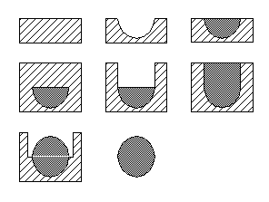
This process is most like the additive processes, but the use of cutting allows contoured surfaces on the bottom sides of parts. The layers may also be made significantly thicker when the parts are prismatic, or when lower resolutions are acceptable. In the example of Figure 3 a cross section of a sphere being fabricated is shown. Here a large number of layers might give a relatively smooth shape, or a few layers would give a rather rough sphere.
Figure 3 - Production of a sphere in layers using BFS
3.2 Top Facing Surfaces (TFS)
If we also allow machining of top facing surfaces, then we can increase the build speed significantly. The basic steps of the process are outlined below,
1. put down a thick wax layer
2. use NC milling techniques to cut out a cavity
3. fill the cavity with a polymer
4. mill the new surface flat
5. cut any curvatures on the top surface
6. repeat steps 1 to 5 until the part is complete
7. melt wax and remove the completed part
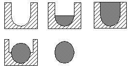
If we reconsider the example of the sphere again, as in Figure 4, we can see a much faster construction. In this case it is possible to build a ball in two layers. This process is obviously more wasteful, but thinner layers could be used to reduce the amount of thermoset that is discarded (remember the thermoplastic can be reused).
Figure 4 - A ball produced in two layers using TFS
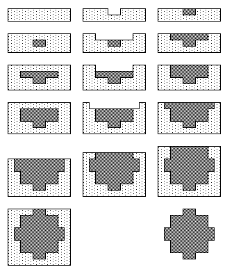
3.3 Constructive Solids Geometry (CSG)
Many modern CAD systems use solid modelling techniques. The users typically enter geometries by adding and subtracting primitive geometries (among other techniques). This method may also be directly supported using the AMP methodology. The basic steps are,
1. create a block of wax larger than the entire part
2. use NC milling techniques to cut out a cavities with the bottom shape of the primitive
3. fill the cavity with a polymer/wax to add/subtract
4. mill the top side of the polymer primitives to finish the upper side of the primitive
5. fill the cavity with wax
6. repeat steps 1 to 5 until the part is complete
7. melt wax and remove the completed part
Figure 5 below shows a ball being made in one step. Here there is also a great wastage of material, but this will also reduce manufacturing time.
Figure 5 - A sphere manufactured in one step using CSG
To fully illustrate the value we can consider a standard CSG example part shown in cross section in Figure 6.
Figure 6 - A complex part produced using CSG
4.0 CONCLUSSIONS
4.1 Advantages/Disadvantages
The AMP process is a compromise between the additive and subtractive processes. As a result it tends to overlap advantages and disadvantages of the various processes. The advantages can be summarized as,
• thicker layers decrease part production time
• makes use of an existing base of NC mills
• materials are inexpensive, and very easy to obtain
• safety concerns are minimized
• existing machining systems provide strong support
• sizes well above 1m/1yd are possible
• parts could be painted during production
• inserts are easy to add
• no assembly is required
• the matrix (e.g., wax) can be collected and reused
The specific disadvantages of this techniques are,
• more sophistication is required in the control software
• intermittent mixing of thermoset materials can be difficult
• shrinkage of materials may require dimensional compensation
4.2 Current Status and Future Work
So far to date this process has been tested by hand and on automatic machines. A specialized machine is near completion, and will be used for further research. A number of problems are still being investigated,
• mixing of polymers in intermittent batches
• automatic generation of tool paths
• alternative materials
This work is the subject of a recent patent application, and will be directed towards industrial applications in the near future.
4.3 Summary
A process was presented that uses a hybrid of additive and subtractive processes for rapid prototyping of parts. The basis of the operation is wax layers that are poured and allowed to harden. Pockets are then cut into these layers, and a hardening polymer is poured in. Once both are solidified, the top of both surfaces is milled flat, and a new layer of wax is added. This continues until the entire part is built up, at which time the wax is melted, and the encased part removed. This process can be done in any machine shop using standard milling machines. The total retail costs for consumable supplies could be less than $20 for a simple model, as compared to capital costs of $50,000+ for an additive process, and typically high material costs. Even more importantly, this process also draws on the experience base of existing machinists, and utilizes an existing infrastructure for machine tools.
AKNOWLEDGEMENTS
I must thank Rob Tremblay, Mark Doogan and Andrew Duncan who built the prototype machine as their undergraduate theses. Also, Jim Vergas and Mark Phoa also examined various aspects of the process for their theses. Funding for this work was derived from internal sources, thus I must thank Dean Bill White for his generous support.
REFERENCES/BIBLIOGRAPHY
[1] Burns, M., 1993, Automated Fabrication: improving productivity in manufacturing, Prentice-Hall, New Jersey.
[2] Cawley, J.D., Heuer, A., Newman, W., 1995, “Solid Freeform Fabrication Directly in to Engineered Ceramics Using CAM-LEM”, a presentation at the ASM Materials Congress, Cleveland, Ohio, October 30th.
[3] Rapid Prototyping Association, 1995, “Advances in Materials”, an article appearing in the Rapid Prototyping newsletter, Society of Manufacturing Engineers, Vol. 1, No. 4, pp. 5-7.
[4] Wohlers, T., 1995, “Rapid Prototyping State of the Industry”, a paper reprint by the Rapid Prototyping Association of the Society of Manufacturing Engineers.