7.1.2 A Mobile Service Robot for the Space Station
• We can see a figure depicting the SPDM for the planned space station.
*********** Include Robot Arm figure
• All discussions in this section are based on the space station manipulator as described in SSP30000.
• The basic functions (at PMC) are classified as,
Category 1 - requires tolerance for two consecutive failures in each system - fail safe/fail operational - basically required 1 prime + 1 redundant + 1 backup
Category 2 - requires tolerance for one failure in each system - failure tolerant - typically requires 1 prime + 1 backup
Category 2S - requires tolerance for one failure in the system - fail operational
• Examples of equipment in the different categories are,
• Category 1 - The orbiter is a time critical system
• Category 2S - Safety monitoring and emergency control systems
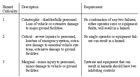
• Recall the following hazard levels, also consider the control requirements,
• For the manipulator (SSRMS) hazards include,
- payload released without command
- orbiter stuck to space station via SSRMS
- orbiter collides with space station because of failed capture (docking with SSRMS).
- motion of arm without command
- no motion in arm in response to command
- orbiter stuck to space station via SSRMS.
- all functions must be safed within 250 ms of occurrence of fault
- can’t report critical failure
- can’t implement alternate operation
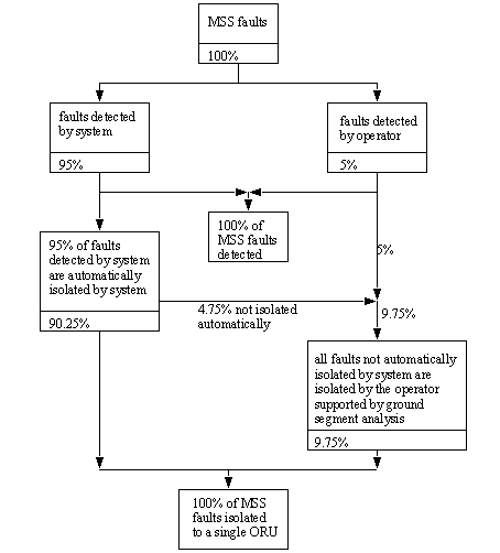
• isolation - we want to estimate the % failures that are prevented from reaching a specific module. Typically these values are,
5% maximum false error indication rate
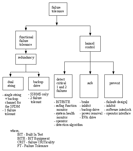
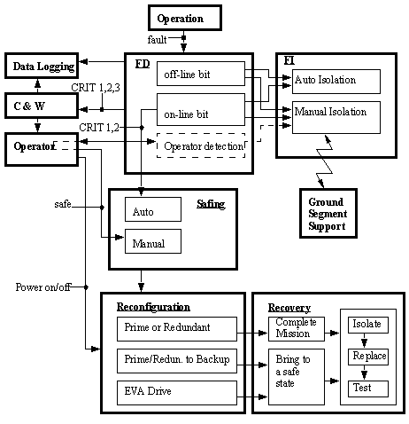
• MSS Failure Tolerance Concept [Brimley]
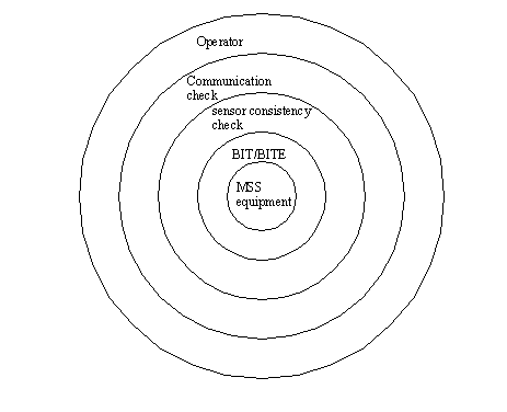
• Failure Detection and Isolation Coverage Scheme [Brimley]
• MSS Failure Management Functional Interfaces [Brimley]
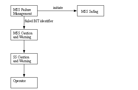
• Layered defense approach for Detection of Sensor Data Failures [Brimley]
- two failure tolerant for orbiter
- provide drive (EVA) for joint and LEE latch mechanisms
- alternate data path/transmission
- reconfiguration time less than 271 seconds
• The purpose for these measures
- when the failure occurs, the software, and hardware engineers must know what their systems are to do. This is the best way to get all to agree.
• operation failure of computational units may include,
- invoking off-line bit checks with error checking algorithms
- operator visual inspections via cameras, etc.
- analysis of units memory through data dumps, etc.
- ground support failure isolation analysis
- exercising equipment with known algorithms
• Note: in the case of SSRMS the operator may use EVA units to move the arm away from contact.
• Operators may always elect to replace failed units, if extras available.
• A diagram of the MSS Failure Management Concept is shown below, [Brimley]. This depicts a scheme for dealing with faults once they are detected. Some of the acronyms used are,
EVA - Extra Vehicular Activity
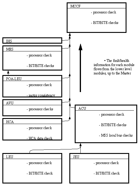
• There is also a scheme for estimating when a system has erred. This is based on a bottom up approach where the checks for errors are made in the specific modules, and then error reports are propagated up to the high level software/hardware. The diagram below depicts the system used in the SSRM.
