ASSIGNMENT PROBLEMS
1. For the transfer functions below, draw the bode plots using computer software.
2. Draw Bode plots for the following functions using straight line approximations.
3. Given the transfer function below,
a) draw the straight line approximation of the bode plot.
b) determine the steady state output if the input is x(s) = 20 cos(9t+.3) using the striaght line plots.
c) use an exact method to verify part b).
4. a) Convert the following differential equation to a transfer function.
b) Apply a phasor (Fourier) transform to the differential equation and develop equations for the system gain and phase shift as a function of input frequency.
c) Draw a Bode plot using the equations found in part b) on the attached log paper.
d) Draw a straight line approximation of the system transfer function on the attached log paper.
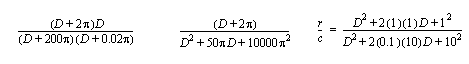
5. For the following transfer function,
a) Draw the Bode plot on the attached semi-log graph paper.
b) Given an input of F=5sin(62.82t), find the output, x, using the Bode plot.
c) Given an input of F=5sin(62.82t), find the output, x, using phasors.
6. For the following transfer function,
a) Draw the Bode plot on the attached semi-log graph paper.
b) Given an input of F=5sin(62.82t), find the output, x, using the Bode plot.
c) Given an input of F=5sin(62.82t), find the output, x, using phasors.
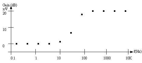
7. Given the experimental Bode (Frequency Response Function) plot below, find a transfer function to model the system. The input is a voltage ‘V’ and the output is a displacement ‘x’. (Hint: after calculating the function use Scilab to verify the results.)
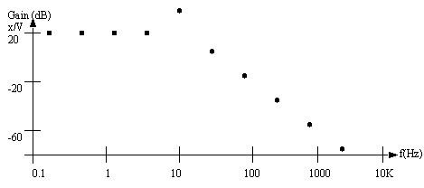
8. Given the experimental Bode (Frequency Response Function) plot below, find a transfer function to model the system. The input is a voltage ‘V’ and the output is a displacement ‘x’. (Hint: after calculating the function use Scilab to verify the results.)