10.23.1 SWITCHED INPUTS AND OUTPUTS
A PLC is just a computer. We must get information in so that it may make decisions and have outputs so that it can make things happen.
Switches - Contact, deadman, etc. all allow a voltage to be applied or removed from an input.
Relays - Used to isolate high voltages from the PLC inputs, these act as switches.
Encoder - Can keep track of positions.
10.23.1.1 - Input Modules
• Input modules typically accept various inputs depending upon specified values.
• DC voltages are usually lower and, therefore, safer (i.e., 12-24V)
• DC inputs are very fast. AC inputs require a longer time (e.g., a 60Hz wave would require 1/60sec for reasonable recognition).
• DC voltages are flexible being able to connect to greater varieties of electrical systems.
• DC input cards typically have more inputs.
• AC signals are more immune to noise than DC, so they are suited to long distances and noisy (magnetic) environments.
• AC signals are very common in many existing automation devices.
10.23.1.2 - Actuators
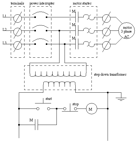
• Inductive loads - Inductance is caused by a coil building up a magnetic field. When a voltage is removed from the coil, the field starts to collapse. As it does this, the magnetic field is changed back to current/voltage. If this change is too sudden, a large voltage spike is created. One way to overcome this is by adding a surge suppressor. One type of design was suggested by Steel McCreery of Omron Canada Ltd.
10.23.1.3 - Output Modules
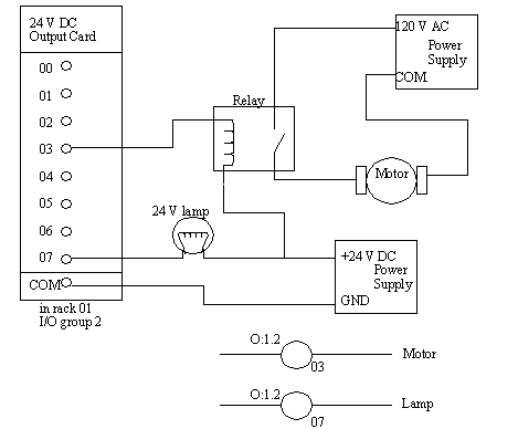
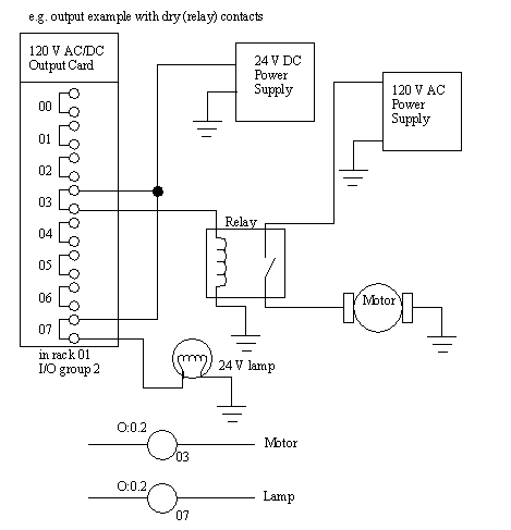
Motors - Motors often have their own controllers, or relays because of the high current they require.
Lights - Lights can often be powered directly from PLC output boards,
• WARNING - ALWAYS CHECK RATED VOLTAGES AND CURRENTS FOR PLC’s AND NEVER EXCEED!
• Typical outputs operate in one of two ways:
Dry contacts - A separate relay is dedicated to each output. This allows mixed voltages (AC or DC and voltage levels up to the maximum) as well as isolated outputs to protect other outputs and the PLC. Response times are often greater than 10ms. This method is the least sensitive to voltage variations and spikes.
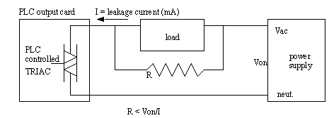
Switched outputs - A voltage is supplied to the PLC card and the card switches it to different outputs using solid state circuitry (transistors, triacs, etc.) Triacs are well suited to AC devices requiring less than an amp. They are sensitive to power spikes and might inadvertently turn on when there are transient voltage spikes. A resistor may need to be put in parallel with a load to ensure enough current is drawn to turn on the triac. The resistor size can be determined by
Transistor outputs use NPN or PNP transistors up to 1A typically. Their response time is well under 1ms.