
Robots are devices that are programmed to move parts, or to do work with a tool. For example, robots are often used to stack boxes on a pallet, or to weld steel plates together. This chapter will introduce the basic concepts behind robotics, and introduce a commercial robot. Following chapters will introduce more robots, and discuss applications.
There is a set of basic terminology and concepts common to all robots. These terms follow with brief explanations of each.
Links and Joints - Links are the solid structural members of a robot, and joints are the movable couplings between them.
Degree of Freedom (dof) - Each joint on the robot introduces a degree of freedom. Each dof can be a slider, rotary, or other type of actuator. Robots typically have 5 or 6 degrees of freedom. 3 of the degrees of freedom allow positioning in 3D space, while the other 2or 3 are used for orientation of the end effector. 6 degrees of freedom are enough to allow the robot to reach all positions and orientations in 3D space. 5 dof requires a restriction to 2D space, or else it limits orientations. 5 dof robots are commonly used for handling tools such as arc welders.
Orientation Axes - Basically, if the tool is held at a fixed position, the orientation determines which direction it can be pointed in. Roll, pitch and yaw are the common orientation axes used. Looking at the figure below it will be obvious that the tool can be positioned at any orientation in space. (imagine sitting in a plane. If the plane rolls you will turn upside down. The pitch changes for takeoff and landing and when flying in a crosswind the plane will yaw.)

Position Axes - The tool, regardless of orientation, can be moved to a number of positions in space. Various robot geometries are suited to different work geometries. (more later)
Tool Centre Point (TCP) - The tool centre point is located either on the robot, or the tool. Typically the TCP is used when referring to the robots position, as well as the focal point of the tool. (e.g. the TCP could be at the tip of a welding torch) The TCP can be specified in cartesian, cylindrical, spherical, etc. coordinates depending on the robot. As tools are changed we will often reprogram the robot for the TCP.
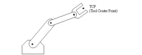
Figure 7.2 - The Tool Center Point (TCP)
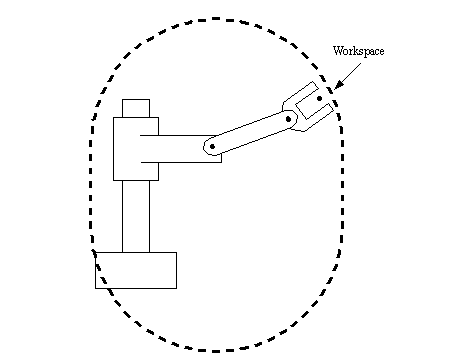
Work envelope/Workspace - The robot tends to have a fixed, and limited geometry. The work envelope is the boundary of positions in space that the robot can reach. For a cartesian robot (like an overhead crane) the workspace might be a square, for more sophisticated robots the workspace might be a shape that looks like a ‘clump of intersecting bubbles’.
Speed - refers either to the maximum velocity that is achievable by the TCP, or by individual joints. This number is not accurate in most robots, and will vary over the workspace as the geometry of the robot changes (and hence the dynamic effects). The number will often reflect the maximum safest speed possible. Some robots allow the maximum rated speed (100%) to be passed, but it should be done with great care.
Payload - The payload indicates the maximum mass the robot can lift before either failure of the robots, or dramatic loss of accuracy. It is possible to exceed the maximum payload, and still have the robot operate, but this is not advised. When the robot is accelerating fast, the payload should be less than the maximum mass. This is affected by the ability to firmly grip the part, as well as the robot structure, and the actuators. The end of arm tooling should be considered part of the payload.
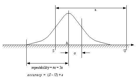
Repeatability - The robot mechanism will have some natural variance in it. This means that when the robot is repeatedly instructed to return to the same point, it will not always stop at the same position. Repeatability is considered to be +/-3 times the standard deviation of the position, or where 99.5% of all repeatability measurements fall. This figure will vary over the workspace, especially near the boundaries of the workspace, but manufacturers will give a single value in specifications.
Accuracy - This is determined by the resolution of the workspace. If the robot is commanded to travel to a point in space, it will often be off by some amount, the maximum distance should be considered the accuracy. This is an effect of a control system that is not necessarily continuous.
Settling Time - During a movement, the robot moves fast, but as the robot approaches the final position is slows down, and slowly approaches. The settling time is the time required for the robot to be within a given distance from the final position.
Control Resolution - This is the smallest change that can be measured by the feedback sensors, or caused by the actuators, whichever is larger. If a rotary joint has an encoder that measures every 0.01 degree of rotation, and a direct drive servo motor is used to drive the joint, with a resolution of 0.5 degrees, then the control resolution is about 0.5 degrees (the worst case can be 0.5+0.01).
Coordinates - The robot can move, therefore it is necessary to define positions. Note that coordinates are a combination of both the position of the origin and orientation of the axes.
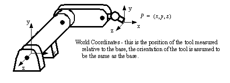
Figure 7.3 - World Coordinates - To Locate the TCP

Figure 7.4 - Tool Coordinates - Describing Positions Relative to the Tool
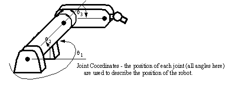
Figure 7.5 - Joint Coordinates - the Positions of the Actuators
• The accuracy and repeatability are functions of,
- resolution- the use of digital systems, and other factors mean that only a limited number of positions are available. Thus user input coordinates are often adjusted to the nearest discrete position.
- kinematic modeling error - the kinematic model of the robot does not exactly match the robot. As a result the calculations of required joint angles contain a small error.
- calibration errors - The position determined during calibration may be off slightly, resulting in an error in calculated position.
- random errors - problems arise as the robot operates. For example, friction, structural bending, thermal expansion, backlash/slip in transmissions, etc. can cause variations in position.
• “How close does the robot get to the desired point”
• This measures the distance between the specified position, and the actual position of the robot end effector.
• Accuracy is more important when performing off-line programming, because absolute coordinates are used.
• “How close will the robot be to the same position as the same move made before”
• A measure of the error or variability when repeatedly reaching for a single position.
• This is the result of random errors only
• repeatability is often smaller than accuracy.
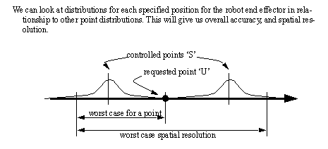
• Resolution is based on a limited number of points that the robot can be commanded to reach for, these are shown here as black dots. These points are typically separated by a millimeter or less, depending on the type of robot. This is further complicated by the fact that the user might ask for a position such as 456.4mm, and the system can only move to the nearest millimeter, 456mm, this is the accuracy error of 0.4mm.
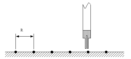
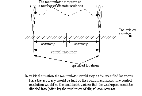
• In a perfect mechanical situation the accuracy and control resolution would be determined as below,
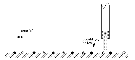
• Kinematic and calibration errors basically shift the points in the workspace resulting in an error ‘e’. Typically vendor specifications assume that calibration and modeling errors are zero.
• Random errors will prevent the robot from returning to the exact same location each time, and this can be shown with a probability distribution about each point.
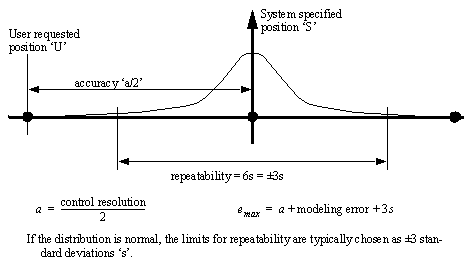
• The fundamental calculations are,
• Spatial resolution is the smallest increment of movement into which the robot can divide its work volume. Spatial resolution depends on two factors: the systems control resolution and the robots mechanical inaccuracies. It is easiest to conceptualize these factors in terms of a robot with 1 degree of freedom.
• Control resolution - is determined by the robot’s position control system and its feedback measurement system. It is the controllers ability to divide the total range of movement for the particular joint into individual increments that can be addressed in the controller. The increments are sometimes referred to as “addressable parts”. The ability to divide the joint range into increments depends on the bit storage capacity in the control memory. The number of separate, identifiable increments (addressable points) for a particular axis is,

• example - A robot with 8 bit control resolution can divide a motion range into 256 discrete positions. The control resolution is about (range of motion)/256. The increments are almost always uniform and equal.
• If mechanical inaccuracies are negligible, Accuracy = Control Resolution/2
• The payload is always specified as a maximum value, this can be before failure, or more commonly, before serious performance loss.
- gravity effects cause downward deflection of the arm and support systems
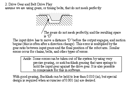
- drive gears and belts often have noticeable amounts of slack (backlash) that cause positioning errors
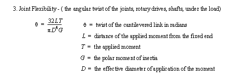
- joint play (windup) - when long rotary members are used in a drive system and twist under load
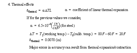
- thermal effects - temperature changes lead to dimensional changes in the manipulator
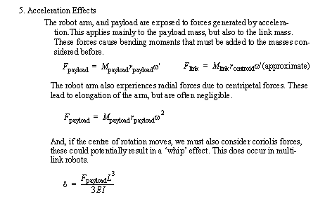
- acceleration effects - inertial forces can lead to deflection in structural members. These are normally only problems when a robot is moving very fast, or when a continuous path following is essential. (But, of course, during the design of a robot these factors must be carefully examined)
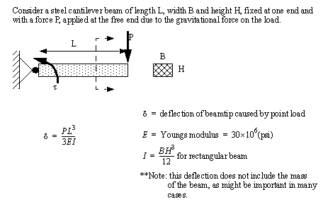
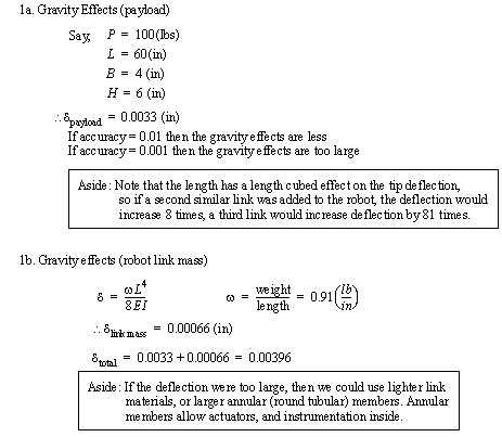

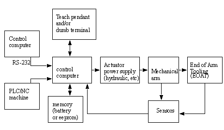
• The basic components of a robot are,
Structure - the mechanical structure (links, base, etc). This requires a great deal of mass to provide enough structural rigidity to ensure minimum accuracy under varied payloads.
Actuators - The motors, cylinders, etc. that drive the robot joints. This might also include mechanisms for a transmission, locking, etc.
Control Computer - This computer interfaces with the user, and in turn controls the robot joints.
End of Arm Tooling (EOAT) - The tooling is provided be the user, and is designed for specific tasks.
Teach pendant - One popular method for programming the robot. This is a small hand held device that can direct motion of the robot, record points in motion sequences, and begin replay of sequences. More advance pendants include more functionality.
• Robots come in a wide variety of shapes, and configurations.
• The major classes of robots include,
arms - fixed in place, but can reach and manipulate parts and tools
mobile - these robots are free to move
Revolute - rotary joints often driven by electric motors and chain/belt/gear transmissions, or by hydraulic cylinders and levers.
Prismatic - slider joints in which the link is supported on a linear slider bearing, and linearly actuated by ball screws and motors or cylinders.
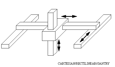
Cartesian/Rectilinear/Gantry - Positioning is done in the workspace with prismatic joints. This configuration is well used when a large workspace must be covered, or when consistent accuracy is expected from the robot.
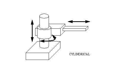
Cylindrical - The robot has a revolute motion about a base, a prismatic joint for height, and a prismatic joint for radius. This robot is well suited to round workspaces.
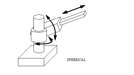
Spherical - Two revolute joints and one prismatic joint allow the robot to point in many directions, and then reach out some radial distance.
Articulated/Jointed Spherical/Revolute - The robot uses 3 revolute joints to position the robot. Generally the work volume is spherical. This robot most resembles the human arm, with a waist, shoulder, elbow, wrist.
Scara (Selective Compliance Arm for Robotic Assembly) - This robot conforms to cylindrical coordinates, but the radius and rotation is obtained by a two planar links with revolute joints.
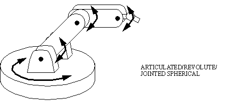
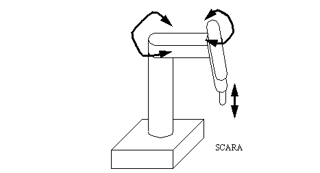
• The robots discussed up to this point have concerned ‘arms’ that are fixed to the floor. Another important class of robots are autonomous, and free to move about the workspace.
- Automatic Guided Vehicles in factories
• These are typically wheeled robots that carry payloads through a factory.
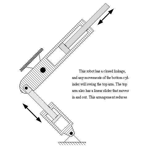
• The mechanical structure of the robot has a major influence over performance. Typically closed kinematic chains give higher strengths, but lower speeds and flexibility.
• The linkage shown below uses two cylinders (hydraulic or pneumatic) to give radial positioning
• There are a large number of power sources that may be used for robots.
- hard to do continuous control
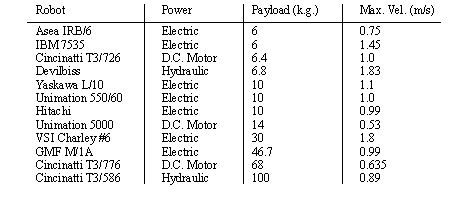
• Actuators lead to various payload capabilities as shown in the following list.
Repeatability (based on constant temp., load, speed) +/- 0.3mm
Operating Temperature 5C to 40C
Humidity (based on constant temp. load, speed) 10% to 85%
Power Requirements 120/220/230/240 VAC
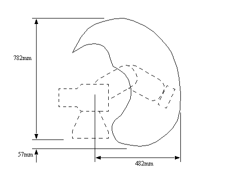
• The workspace is pictured below,
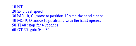
• All comments follow a semi-colon at any position on a line
• Statements are ended with a colon, and as long as colons are used, more than one statement can be used on a line.
• Dimensions are given in millimeters in the programs.
• A sample program is given below with comments for explanation,
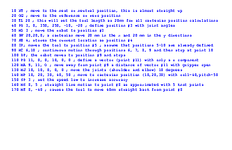
• The example below shows how points are defined and used. Please be aware that point location values are not normally defined in a program. Normally they are programmed by hand, and then when the program is run, it refers to them by number (from 1 to 629)
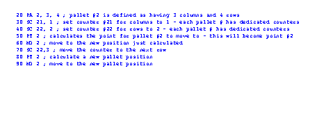
• The example below shows how we can define and use pallets. The definition of a pallet covers a number of lines to define the pallet size and then the location. We must also define points to indicate where the pallet lies in space. For the example below these points would have to be position numbers 20 (pallet origin), 21 (origin to end of first column), 22 (origin to end of first row), 23 (origin to diagonal corner of pallet). Note: if using pallet #3 these counters would be 30-33, and point 3 would move.
• The example below shows some of the position commands. These positions are normally defined outside the program by moving the robot to desired locations. These positions are not always absolute, and in some cases will act as displacement vectors.

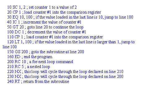
• The example below shows some of the counter and branching functions. These tend to use a status register approach - for example, a value to be compared will be loaded on one line, the next line will compare it and a branch instruction will occur on the specified condition. For-next loops have been constructed as part of this example.
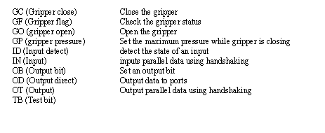
• The example below shows how to use various gripper and I/O functions. There are eight input bits and 8 output bits available.

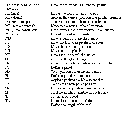
• A summary of the motion commands is given below,
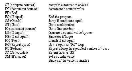
• A summary of the program control commands is given below,
• A summary of the IO commands is given below,
1. a) What are some basic functions expected on a robot teach pendant
b) Describe how a computer can help avoid debug robot programs without a robot being used
2. Write a short program to direct a Mitsubishi RV-M1 robot to pick up and put down a block. Assume the points have already been programmed with the teach pendants.
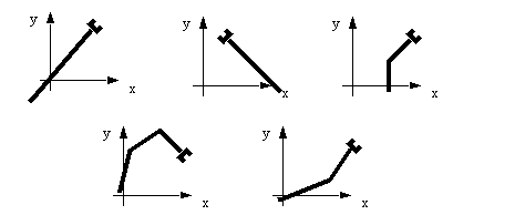
3. What is the workspace for each of the robots below, and can the robots reach all positions and orientations in the workspace?
4. Why are 5 axis enough for some robotic applications (eg. welding) and all NC milling operations?
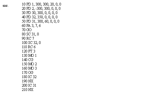
5. You have been asked to write a program for a Mitsubishi RV-M1 robot. The program is to pick up a part at point T1, move to point T2, and then load the part into a pallet. The robot should then return to point A to pick up then next part. This should continue until the pallet is full.
Pallet has 6 rows and 7 columns
Pallet origin T3 = (300, 0, 0)
Pallet end of row T4 = (350, 0, 0)
Pallet end of column T5 = (300, 60, 0)
6. Given the scenario below, find the minimum angular resolution of the rotating sensor.

- the robot has +/- 0.5” accuracy
- the pallet can slide +/- 0.1” on the belt

- the driving motor is continuous, and can be run to any angle
- the rotating sensor is an incremental encoder, every rotation of some small angle it issues a pulse. But, because of the construction of the device, it has a minimum resolution for angular measurements
- the robot must be able to touch the part to pick it up
- the tool on the end of the robot is a 1” magnet, and it must be able to touch the part completely to pick it up.
7. Consider a double jointed manipulator as shown below. It is subjected to a loading at the tip of 8 lbs, and works in a heated environment (i.e. T0(room temp.) = 60°F and T1 (working temp.) = 80°F.
a) Determine the elongation of the manipulator.
b) Determine the total linear deflection of the manipulator.
c) Determine the total final accuracy of the manipulator of the tip of the manipulator.

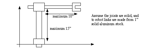
8. For the robot pictured below, assume the that a maximum payload of 10kg is specified. The joints are controlled by stepper motors with 200 steps per revolution. Each of the joints slides, and the gearing is such that 1 revolution of the stepper motor will result in 1” of travel. What is the accuracy of the robot?
9. Consider a double jointed manipulator as shown below. It is subjected to a loading at the tip of 8 lbs, and works in a heated environment (i.e. T0(room temp.) = 60°F and T1 (working temp.) = 80°F.
a) Determine the elongation of the manipulator.
b) Determine the total linear deflection of the manipulator.
c) Determine the total final accuracy of the manipulator of the tip of the manipulator.

Introduction to robots and programming methods.
This laboratory will involve a basic tutorial on the use of the robot, including safety. The students will have prepared a program for the robot, and tested it ahead of class time using the simulator. During the laboratory the robot will be programmed and tested using the prepared programs. A simple accuracy and repeatability test will be conducted.
1. Use Netscape Communicator to access the robots in the laboratory, explore the site.
2. Review the notes on the Mitsubishi RV-M1. After this use the on-line robot to write a simple test program.
3. Write a program to pick up a pop can at one point, and drop it off at a pallet. The program should repeat six times in a row.
1. Follow the robot tutorial, and then examine the robot manual.
2. Set up the pop can feeders and fixtures.
3. Enter your prelab program and modify it as required.
4. If not already done, connect the sensors on the feeders and fixture to the robot controller.
5. Add commands to the program that will examine inputs and take appropriate actions.
6. Put the robot in an extended position (tool far away from the base). Set up a dial gauge indicator so that it touches a solid point on the tool. Set the gauge so that it reads zero. Move the robot away and back to the same position, and read the value from the dial gauge indicator. Repeat this process to get 10 readings.
7. Position the robot so that the tool is in the middle of the workspace. Take similar measurements to those in step 3.
1. A copy of your prelab program.
2. A copy of the programs written during the laboratory.
3. Statistical estimates of repeatability for both positions.
1. Turn on the robot power. The switch is located on the back of the unit.
2. Find the teach pendant (Note: It looks somewhat like a calculator). Turn the switch at the top left to ’on’. This will allow the teach pendant to control the robot.
3. Home the robot by pressing <NST><ENT>. The robot will move each joint to one end of it’s range. This is an important step whenever a robot is turned on to find the end of the range of motion.
4. The robot can be moved to new positions using the buttons on the right hand side of the teach pendant. Use the following buttons to move the arm. Notice that the buttons move one joint at a time.
<B+><B-> - moves the base right/left
<S+><S-> - moves the shoulder up/down
<E+><E-> - moves the elbow up/down
<P+><P-> - pitches the gripper up/down
5. The robot tool (at the end of the arm) can be moved in cartesian coordinates by pressing <XYZ><ENT> and then using the buttons indicated below.
6. The robot tool can be moved relative to the tool’s current orientation by pressing <TOOL><ENT>. The buttons below will move the robot to preserve the tool orientation.
<Z+><Z-> - advance/retract the tool
<P+><P-> - pitch the tool up/down
7. Pressing <PTP><ENT> returns the robot to joint motion mode. While programming robot points an operator will often switch between different robot programming modes.
8. Pressing <ORG><ENT> will move the robot to the origin position where all of the joint angles are equal to zero.
9. At this point we are ready to record positions. This is done by moving the robot to a position and then storing that position in a position memory location. These locations start at zero and go up to 100 (?). Move the robot to three different positions and then record the points using the keystrokes below. (Note: To clear positions you can use <PC><#><ENT> where ’#’ is the position number.)
<PS><1><ENT> - this will record position 1
<PS><2><ENT> - this will record position 2
<PS><3><ENT> - this will record position 3
10. The robot can be moved to points using the keystrokes below. If the last point entered above was ’3’, then it will be the current focus. The commands <INC> and <DEC> will increment and decrement to other positions.
<DEC><ENT> - decrement to position 2
<DEC><ENT> - decrement to position 1
<DEC><ENT> - try to decrement to position 0 - this will cause an error
<INC><ENT> - increment to position 2
<INC><ENT> - increment to position 3
<MOV><1><ENT> - move to position 1
<MOV><2><ENT> - move to position 2
<MOV><3><ENT> - move to position 3
11. Connect the RS-232 port of the robot controller to a PC with a serial cable.
12. Run a terminal emulator on the PC and give it the following settings
13. Turn the teach pendant off. This will allow you to control the robot from the remote terminal.
14. Type in ’NT’ to home the robot. All commands should be typed in UPPER CASE. If an error occurs a tone will be heard. To clear the error press the ’reset’ button on the front of the robot.
15. Type the following commands and observe their effect.
16. Type the following program in a text editor. Cut and paste it into the terminal window when done. This program could be run with ’GT 10’, ’RN 10’ or ’RN’.