When multiple computers are used in a manufacturing facility they need to communicate. One means of achieving this is to use a network to connect many peers. Another approach is to use dedicated communication lines to directly connect two peers. The two main methods for communication are serial and parallel. In serial communications the data is broken down as single bits that are sent one at a time. In parallel communications multiple bits are sent at the same time.
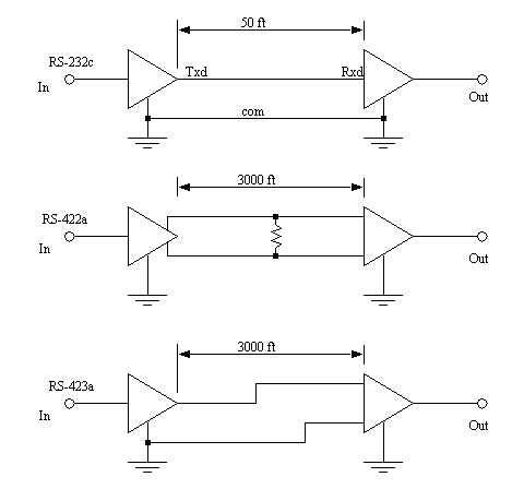
Serial communications send a single bit at a time between computers. This only requires a single communication channel, as opposed to 8 channels to send a byte. With only one channel the costs are lower, but the communication rates are slower. The communication channels are often wire based, but they may also be optical and radio. Figure 22.2 shows some of the standard electrical connections. RS-232c is the most common standard that is based on a voltage level change. At the sending computer an input will either be true or false. The ’line driver’ will convert a false value ’in’ to a ’Txd’ voltage between +3V to +15V, true will be between -3V to -15V. A cable connects the ’Txd’ and ’com’ on the sending computer to the ’Rxd’ and ’com’ inputs on the receiving computer. The receiver converts the positive and negative voltages back to logic voltage levels in the receiving computer. The cable length is limited to 50 feet to reduce the effects of electrical noise. When RS-232 is used on the factory floor, care is required to reduce the effects of electrical noise - careful grounding and shielded cables are often used.

The RS-422a cable uses a 20 mA current loop instead of voltage levels. This makes the systems more immune to electrical noise, so the cable can be up to 3000 feet long. The RS-423a standard uses a differential voltage level across two lines, also making the system more immune to electrical noise, thus allowing longer cables. To provide serial communication in two directions these circuits must be connected in both directions.
To transmit data, the sequence of bits follows a pattern, like that shown in Figure 22.3. The transmission starts at the left hand side. Each bit will be true or false for a fixed period of time, determined by the transmission speed.
A typical data byte looks like the one below. The voltage/current on the line is made true or false. The width of the bits determines the possible bits per second (bps). The value shown before is used to transmit a single byte. Between bytes, and when the line is idle, the ’Txd’ is kept true, this helps the receiver detect when a sender is present. A single start bit is sent by making the ’Txd’ false. In this example the next eight bits are the transmitted data, a byte with the value 18. The data is followed by a parity bit that can be used to check the byte. In this example there are two data bits set, and even parity is being used, so the parity bit is set. The parity bit is followed by two stop bits to help separate this byte from the next one.
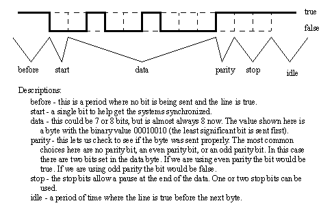
Some of the byte settings are optional, such as the number of data bits (7 or 8), the parity bit (none, even or odd) and the number of stop bits (1 or 2). The sending and receiving computers must know what these settings are to properly receive and decode the data. Most computers send the data asynchronously, meaning that the data could be sent at any time, without warning. This makes the bit settings more important.
Another method used to detect data errors is half-duplex and full-duplex transmission. In half-duplex transmission the data is only sent in one direction. But, in full-duplex transmission a copy of any byte received is sent back to the sender to verify that it was sent and received correctly. (Note: if you type and nothing shows up on a screen, or characters show up twice you may have to change the half/full duplex setting.)
The transmission speed is the maximum number of bits that can be sent per second. The units for this is ’baud’. The baud rate includes the start, parity and stop bits. For example a 9600 baud transmission of the data in Figure 22.3 would transfer up to  bytes each second. Lower baud rates are 120, 300, 1.2K, 2.4K and 9.6K. Higher speeds are 19.2K, 28.8K and 33.3K. (Note: When this is set improperly you will get many transmission errors, or ’garbage’ on your screen.)
Serial lines have become one of the most common methods for transmitting data to instruments: most personal computers have two serial ports. The previous discussion of serial communications techniques also applies to devices such as modems.
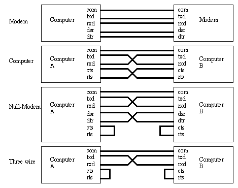
The RS-232c standard is based on a low/false voltage between +3 to +15V, and an high/true voltage between -3 to -15V (+/-12V is commonly used). Figure 22.4 shows some of the common connection schemes. In all methods the ’txd’ and ’rxd’ lines are crossed so that the sending ’txd’ outputs are into the listening ’rxd’ inputs when communicating between computers. When communicating with a communication device (modem), these lines are not crossed. In the ’modem’ connection the ’dsr’ and ’dtr’ lines are used to control the flow of data. In the ’computer’ the ’cts’ and ’rts’ lines are connected. These lines are all used for handshaking, to control the flow of data from sender to receiver. The ’null-modem’ configuration simplifies the handshaking between computers. The three wire configuration is a crude way to connect to devices, and data can be lost.
Common connectors for serial communications are shown in Figure 22.5. These connectors are either male (with pins) or female (with holes), and often use the assigned pins shown. The DB-9 connector is more common now, but the DB-25 connector is still in use. In any connection the ’RXD’ and ’TXD’ pins must be used to transmit and receive data. The ’COM’ must be connected to give a common voltage reference. All of the remaining pins are used for ’handshaking’.
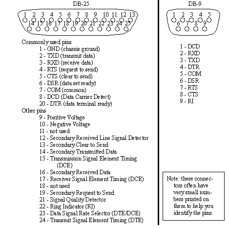
The ’handshaking’ lines are to be used to detect the status of the sender and receiver, and to regulate the flow of data. It would be unusual for most of these pins to be connected in any one application. The most common pins are provided on the DB-9 connector, and are also described below.
TXD/RXD - (transmit data, receive data) - data lines
DCD - (data carrier detect) - this indicates when a remote device is present
RI - (ring indicator) - this is used by modems to indicate when a connection is about to be made.
CTS/RTS - (clear to send, ready to send)
DSR/DTR - (data set ready, data terminal ready) these handshaking lines indicate when the remote machine is ready to receive data.
COM - a common ground to provide a common reference voltage for the TXD and RXD.
When a computer is ready to receive data it will set the "CTS" bit, the remote machine will notice this on the ’RTS’ pin. The ’DSR’ pin is similar in that it indicates the modem is ready to transmit data. ’XON’ and ’XOFF’ characters are used for a software only flow control scheme.
In Linux serial communications is similar to normal file access. The file names used to access these ports are in the ’dev’ directory. The ’com1’ port is called ’ttyS0’, and the ’com2’ port is called ’ttyS1’.
int fd; /* File Descriptor Global Variable */
Figure X.10 - The Header File (serial_io.h)
int param_parity; // not implemented yet
int param_flow; // not implemented yet
serial_io::serial_io(char *args){
param_baud = B9600; // set defaults
for(i = 0; (i < len) && (error == NO_ERROR); i++){
error = decode_param(&(temp[last]));
error = decode_param(&(temp[last]));
if((error == NO_ERROR) && (param_file_name != NULL)){
if((fd = open(param_file_name /*args[0] port "/dev/ttyS0"*/, O_RDWR | O_NOCTTY | O_NDELAY)) < 0){
printf("Unable to open serial port\n");
/* Get the current options for the port */
cfsetispeed(&options, param_baud); /* Set the baud */
cfsetospeed(&options, param_baud);
options.c_cflag |= (CLOCAL | CREAD);
// enable receiver and set local mode
// Mask the character size to 8 bits, no parity
options.c_cflag |= param_size;
// options.c_cflag &= ~CRTSCTS;
// Disable hardware flow control
// options.c_lflag &= ~(ICANON | ECHO | ISIG);
tcsetattr(fd, TCSANOW, &options);
if(param_file_name != NULL) delete param_file_name;
int serial_io::decode_param(char*parameter){
if(param_file_name != NULL) delete param_file_name;
param_file_name = new char[strlen(parameter)];
strcpy(param_file_name, &(parameter[1]));
} else if(parameter[0] == ’B’){
if(temp == 9600) param_baud = B9600;
if(temp == 2400) param_baud = B2400;
if(temp == 1200) param_baud = B1200;
} else if(parameter[0] == ’D’){
if(temp == 8) param_size = CS8;
if(temp == 7) param_size = CS7;
printf("Did not recognize serial argument type - ignoring\n");
int serial_io::reader(char *text, int max){
char_read = read(fd, text, max-1);
if((text[i] == 10 /*CR*/) || (text[i] == ’\n’)){
for(j = i+1; j <= char_read; j++){
printf("Serial port is not initialized\n");
int serial_io::writer(char *text)
for(count = 0; count < length; count++){
printf("Serial port not initialized\n");
Figure X.11 - Serial Communication Drivers (serial_io.c)
serial = new serial_io("B9600,F/dev/ttyS0");
if(serial->reader(in, 100) != ERROR){
sprintf(out, "ECHO: %s\n", in);
printf("Sending String: %s", out);
Figure X.12 - A Serial Communication Program (serial.c)
These programs can be compiled with the makefile in Figure X.13.
$(CC) $(CFLAGS) serial.c -o serial serial_io.o
serial_io.o: serial_io.c serial_io.h
$(CC) $(CFLAGS) -c serial_io.c
Parallel data transmission will transmit multiple bits at the same time over multiple wires. This does allow faster data transmission rates, but the connectors and cables become much larger, more expensive and less flexible. These interfaces still use handshaking to control data flow.
These interfaces are common for computer printer cables and short interface cables, but they are uncommon on PLCs. A list of common interfaces follows.
Centronics printer interface - These are the common printer interface used on most personal computers. It was made popular by the now defunct Centronics printer company.
GPIB/IEEE-488 - (General Purpose Instruments Bus) This bus was developed by Hewlett Packard Inc. for connecting instruments. It is still available as an option on many new instruments.
To achieve a basic understanding of the serial communication hardware and software.
1. Enter the C++ code found in the chapter.
1. Set up two computers beside each other, at least one should be a Linux computer.
2. Select the right connectors for the serial ports (9 or 25 pin, and male or female) on the computers and build a null modem RS-232 cable to connect the two computers.
3. Start a serial communication program on both of the computers, and establish communications - this will require you to change communication settings.
3a. (Linux) You may use ’minicom’, you will have to be logged in as root, or change the settings for the serial port with ’chmod 666 /dev/ttyS0’ or ’chmod 666 /dev/ttyS1’.
3b. (Windows) Use the hyperterm program ’hypertrm.exe’. When prompted for connection information select ’cancel’.
4. Enter and run the C++ program to echo serial data.
5. Modify the number guess game developed in a previous lab to operate over the serial port.
1. The source code listings for the game running on the serial port.
To use a serial interface to communicate with a stepper motor controller.
A stepper motor is unlike other motors. When a voltage is applied the motor does not turn continuously, it only moves a small increment. There are normally a set of four or more inputs. When these are turned on-off in a set pattern the motor shaft will rotate forward or backwards. A typical stepper motor might have 200 steps per revolution, or steps of 1.8 degrees. These motors often require somewhat sophisticated controllers. One type of controller is called an indexer. It can be given commands to move the motor, and then it takes care of pulsing the motor outputs to drive the motion.
The stepper motor controllers to be used in this laboratory are integrated into the turntables in the material handling system. The controller is integrated into the turntable stations so that it can rotate the turntable up to 360 degrees with a stepped motor, eject a cart using two outputs to solenoid valves, and detect a cart present with a diffuse photoelectric sensor. The controller has an RS-422 port that can be used to communicate, and load programs. This will be connected to an RS-232C port using a special interface cable that converts the current loop to voltage values. The communication settings for the turntables are 9600 baud, 8 data bits, no parity, 1 stop bits, no flow control.
The programming commands for the controller are summarized below.
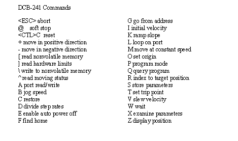
Figure X.14 - Stepper Motor Control Board Commands (DCB-241)
When writing programs command lines can be up to 15 characters long, including spaces. Spaces are used to separate commands and arguments. Characters used in programs can be either upper or lower case. A sample program is given below.
1. Go to the web site www.stepcontrol.com and look at the product documents for the DCB-241 stepper driver.
1. Use a terminal program to communicate with the stepper motor controller. You will need a special communication cable, and the boxes can be opened with a flat bladed screwdriver. Plug the communication cable into the lower connector. (Note: if the unit already has power don’t touch the exposed 120Vac power on the power supply.) Connect an air supply and power to the unit. (Note: don’t forget to turn on the power on the front of the cabinet.)
2. Use the following commands (in sequence) to verify that the turntable is operating properly, and to explore basic commands. (Note: comments are provided for understanding, but should not be entered into the controller.)
<CTRL>C -- this should reset the unit
<SPACE> -- this should print out the line ’V2.03’, if not there are problems
<ENTER> -- this should print ’#’
Z -- read the current position
O -- set the current position as the origin
Z -- print the current position
R1000 -- this should rotate the turntable
R-1000 -- this should rotate the turntable the other way
A8 - kicks the cart one way (notice the lights on the solenoids)
A16 - kicks the cart the other way
] -- this will check the input ports, bits 7 and 8 are for the cart present detectors
3. Enter the following program so that the turntable operates automatically. The list below also includes the commands to download and enter the program. Again comments should not be entered, and line numbers are automatically generated. When the program has been entered it can be run with the command ’G0’.
P0 -- put the controller in programming mode and start the program at location ’0’
0 O0 -- set the current position to the origin with a value of 0
4 R10000 -- more the controller 10000 steps in the positive direction
8 W0 -- wait until ’0’ ms after the motion is complete
11 R-10000 -- move 10000 steps in the opposite direction
15 W100 -- wait until ’100’ ms after the motion is complete
18 J 4 3 -- jump to address ’4’ four (3+1) times, a basic for loop (you may need to change ’4’ if your line numbers don’t match)
27 A0 - shut off the solenoid valve
29 P0 -- the end of the program
4. Write a C++ program to communicate with the stepper motor controller over RS-232. It should allow the user to enter a motor position from the keyboard, and the controller should automatically move.