10.3 PRESENCE DETECTIONThere are two basic ways to detect object presence; contact and proximity. Contact implies that there is mechanical contact and a resulting force between the sensor and the object. Proximity indicates that the object is near, but contact is not required. The following sections examine different types of sensors for detecting object presence. These sensors account for a majority of the sensors used in applications. 10.3.1 Contact SwitchesContact switches are available as normally open and normally closed. Their housings are reinforced so that they can take repeated mechanical forces. These often have rollers and wear pads for the point of contact. Lightweight contact switches can be purchased for less than a dollar, but heavy duty contact switches will have much higher costs. Examples of applications include motion limit switches and part present detectors. 10.3.2 Reed SwitchesReed switches are very similar to relays, except a permanent magnet is used instead of a wire coil. When the magnet is far away the switch is open, but when the magnet is brought near the switch is closed as shown in Figure 10.49 Reed Switch. These are very inexpensive an can be purchased for a few dollars. They are commonly used for safety screens and doors because they are harder to trick than other sensors. 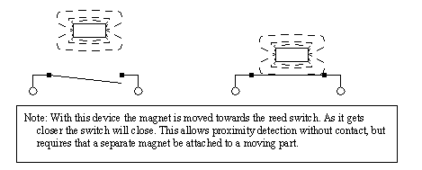
10.3.3 Optical (Photoelectric) SensorsLight sensors have been used for almost a century - originally photocells were used for applications such as reading audio tracks on motion pictures. But modern optical sensors are much more sophisticated. Optical sensors require both a light source (emitter) and detector. Emitters will produce light beams in the visible and invisible spectrums using LEDs and laser diodes. Detectors are typically built with photodiodes or phototransistors. The emitter and detector are positioned so that an object will block or reflect a beam when present. A basic optical sensor is shown in Figure 10.50 A Basic Optical Sensor. 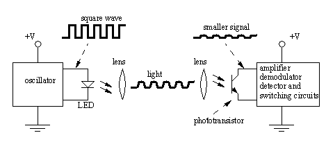
In the figure the light beam is generated on the left, focused through a lens. At the detector side the beam is focused on the detector with a second lens. If the beam is broken the detector will indicate an object is present. The oscillating light wave is used so that the sensor can filter out normal light in the room. The light from the emitter is turned on and off at a set frequency. When the detector receives the light it checks to make sure that it is at the same frequency. If light is being received at the right frequency then the beam is not broken. The frequency of oscillation is in the KHz range, and too fast to be noticed. A side effect of the frequency method is that the sensors can be used with lower power at longer distances. An emitter can be set up to point directly at a detector, this is known as opposed mode. When the beam is broken the part will be detected. This sensor needs two separate components, as shown in Figure 10.51 Opposed Mode Optical Sensor. This arrangement works well with opaque and reflective objects with the emitter and detector separated by distances of up to hundreds of feet. 
Having the emitter and detector separate increases maintenance problems, and alignment is required. A preferred solution is to house the emitter and detector in one unit. But, this requires that light be reflected back as shown in Figure 10.52 Retroreflective Optical Sensor. These sensors are well suited to larger objects up to a few feet away. 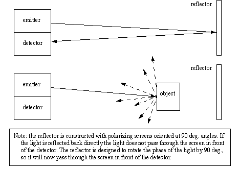
In the figure, the emitter sends out a beam of light. If the light is returned from the reflector most of the light beam is returned to the detector. When an object interrupts the beam between the emitter and the reflector the beam is no longer reflected back to the detector, and the sensor becomes active. A potential problem with this sensor is that reflective objects could return a good beam. This problem is overcome by polarizing the light at the emitter (with a filter), and then using a polarized filter at the detector. The reflector uses small cubic reflectors and when the light is reflected the polarity is rotated by 90 degrees. If the light is reflected off the object the light will not be rotated by 90 degrees. So the polarizing filters on the emitter and detector are rotated by 90 degrees, as shown in Figure 10.53 Polarized Light in Retroreflective Sensors. The reflector is very similar to reflectors used on bicycles. 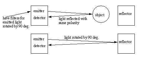
For retroreflectors the reflectors are quite easy to align, but this method still requires two mounted components. A diffuse sensors is a single unit that does not use a reflector, but uses focused light as shown in Figure 10.54 Diffuse Optical Sensor. 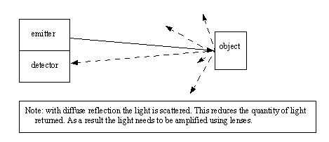
Diffuse sensors use light focused over a given range, and a sensitivity adjustment is used to select a distance. These sensors are the easiest to set up, but they require well controlled conditions. For example if it is to pick up light and dark colored objects problems would result. When using opposed mode sensors the emitter and detector must be aligned so that the emitter beam and detector window overlap, as shown in Figure 10.55 Beam Divergence and Alignment. Emitter beams normally have a cone shape with a small angle of divergence (a few degrees of less). Detectors also have a cone shaped volume of detection. Therefore when aligning opposed mode sensor care is required not just to point the emitter at the detector, but also the detector at the emitter. Another factor that must be considered with this and other sensors is that the light intensity decreases over distance, so the sensors will have a limit to separation distance. 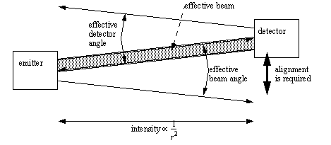
If an object is smaller than the width of the light beam it will not be able to block the beam entirely when it is in front as shown in Figure 10.56 The Relationship Between Beam Width and Object Size. This will create difficulties in detection, or possibly stop detection altogether. Solutions to this problem are to use narrower beams, or wider objects. Fiber optic cables may be used with an opposed mode optical sensor to solve this problem, however the maximum effective distance is reduced to a couple feet. 
Separated sensors can detect reflective parts using reflection as shown in Figure 10.57 Detecting Reflecting Parts. The emitter and detector are positioned so that when a reflective surface is in position the light is returned to the detector. When the surface is not present the light does not return. 
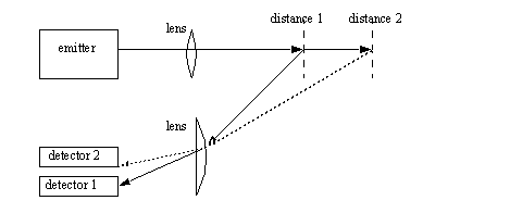
Other types of optical sensors can also focus on a single point using beams that converge instead of diverge. The emitter beam is focused at a distance so that the light intensity is greatest at the focal distance. The detector can look at the point from another angle so that the two centerlines of the emitter and detector intersect at the point of interest. If an object is present before or after the focal point the detector will not see the reflected light. This technique can also be used to detect multiple points and ranges, as shown in Figure 10.59 Multiple Point Detection Using Optics where the net angle of refraction by the lens determines which detector is used. This type of approach, with many more detectors, is used for range sensing systems. 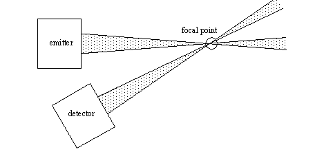
Some applications do not permit full sized photooptic sensors to be used. Fiber optics can be used to separate the emitters and detectors from the application. Some vendors also sell photosensors that have the phototransistors and LEDs separated from the electronics. Light curtains are an array of beams, set up as shown in Figure 10.60 A Light Curtain. If any of the beams are broken it indicates that somebody has entered a workcell and the machine needs to be shut down. This is an inexpensive replacement for some mechanical cages and barriers. 
The optical reflectivity of objects varies from material to material as shown in Figure 10.61 Table of Reflectivity Values for Different Materials [Banner Handbook of Photoelectric Sensing]. These values show the percentage of incident light on a surface that is reflected. These values can be used for relative comparisons of materials and estimating changes in sensitivity settings for sensors. 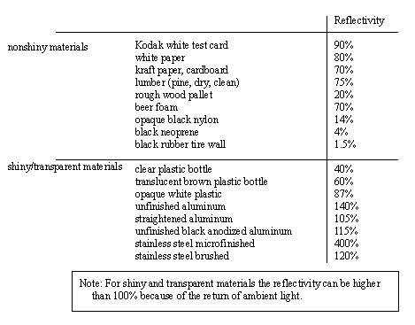
10.3.4 Capacitive SensorsCapacitive sensors are able to detect most materials at distances up to a few centimeters. Recall the basic relationship for capacitance. 
In the sensor the area of the plates and distance between them is fixed. But, the dielectric constant of the space around them will vary as different materials are brought near the sensor. An illustration of a capacitive sensor is shown in Figure 10.62 A Capacitive Sensor. an oscillating field is used to determine the capacitance of the plates. When this changes beyond a selected sensitivity the sensor output is activated. 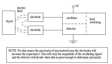
These sensors work well for insulators (such as plastics) that tend to have high dielectric coefficients, thus increasing the capacitance. But, they also work well for metals because the conductive materials in the target appear as larger electrodes, thus increasing the capacitance as shown in Figure 10.63 Dielectrics and Metals Increase the Capacitance. In total the capacitance changes are normally in the order of pF. 
The sensors are normally made with rings (not plates) in the configuration shown in Figure 10.64 Electrode Arrangement for Capacitive Sensors. In the figure the two inner metal rings are the capacitor electrodes, but a third outer ring is added to compensate for variations. Without the compensator ring the sensor would be very sensitive to dirt, oil and other contaminants that might stick to the sensor. 
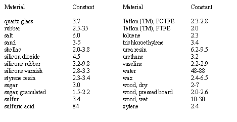
A table of dielectric properties is given in Figure 10.65 Dielectric Constants of Various Materials [Turck Proximity Sensors Guide]. This table can be used for estimating the relative size and sensitivity of sensors. Also, consider a case where a pipe would carry different fluids. If their dielectric constants are not very close, a second sensor may be desired for the second fluid. 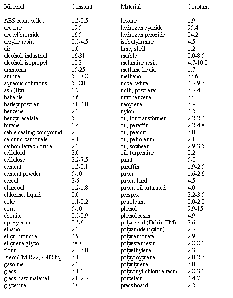
The range and accuracy of these sensors are determined mainly by their size. Larger sensors can have diameters of a few centimeters. Smaller ones can be less than a centimeter across, and have smaller ranges, but more accuracy. 10.3.5 Inductive SensorsInductive sensors use currents induced by magnetic fields to detect nearby metal objects. The inductive sensor uses a coil (an inductor) to generate a high frequency magnetic field as shown in Figure 10.66 Inductive Proximity Sensor. If there is a metal object near the changing magnetic field, current will flow in the object. This resulting current flow sets up a new magnetic field that opposes the original magnetic field. The net effect is that it changes the inductance of the coil in the inductive sensor. By measuring the inductance the sensor can determine when a metal have been brought nearby. These sensors will detect any metals, when detecting multiple types of metal multiple sensors are often used. 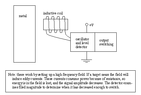
The sensors can detect objects a few centimeters away from the end. But, the direction to the object can be arbitrary as shown in Figure 10.67 Shielded and Unshielded Sensors. The magnetic field of the unshielded sensor covers a larger volume around the head of the coil. By adding a shield (a metal jacket around the sides of the coil) the magnetic field becomes smaller, but also more directed. Shields will often be available for inductive sensors to improve their directionality and accuracy. 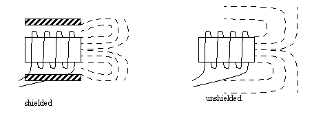
10.3.6 UltrasonicAn ultrasonic sensor emits a sound above the normal hearing threshold of 16KHz. The time that is required for the sound to travel to the target and reflect back is proportional to the distance to the target. The two common types of sensors are; electrostatic - uses capacitive effects. It has longer ranges and wider bandwidth, but is more sensitive to factors such as humidity. piezoelectric - based on charge displacement during strain in crystal lattices. These are rugged and inexpensive. These sensors can be very effective for applications such as fluid levels in tanks and crude distance measurement. 10.3.7 Hall EffectHall effect switches are basically transistors that can be switched by magnetic fields. Their applications are very similar to reed switches, but because they are solid state they tend to be more rugged and resist vibration. Automated machines often use these to do initial calibration and detect end stops. 10.3.8 Fluid FlowWe can also build more complex sensors out of simpler sensors. The example in Figure 10.68 Flow Rate Detection With an Inductive Proximity Switch shows a metal float in a tapered channel. As the fluid flow rate increases the pressure forces the float upwards. The tapered shape of the float ensures an equilibrium position proportional to flowrate. An inductive proximity sensor can be positioned so that it will detect when the float has reached a certain height, and the system has reached a given flowrate. 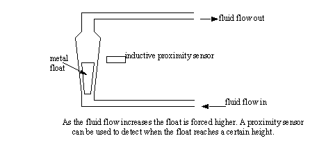
|