8.3 Gears
• When forces become large we cannot count on friction for rolling contact (no slip). Gears use metal teeth that are meshed together to transmit motion between moving components.
8.3.1 Spur Gears
• Spur gears are in very wide use throughout engineering.
• These gears are flat, and either circular or straight (a rack).
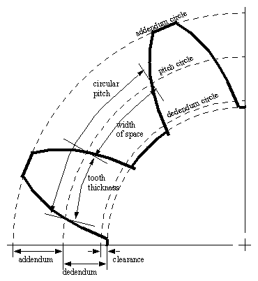
• The figure below shows a typical gear with common terms marked,
egr352a0.jpg
• When gears are properly mated their pitch circles will be tangent. And the faces of the teeth will touch along the addendum and dedendum surfaces, down to the clearance circles.
• Some terms of use when discussing gears,
backlash - the difference is the gap between gear teeth where they mesh. This leads to ‘play’ in the gears.
pinion - a smaller gear
wheel - a larger gear
• diametral pitch is defined by,
• module is defined by,
• The following relationships are also applicable,
• The ratio between angular velocities of two gears can be determined with the law of gearing,
• As seen above the law of gearing assumes that the pitch point is found at a constant radius. If this were to move the driven gear would accelerate /decelerate as the teeth mesh and separate.
• To keep the gears meshing constantly an involute profile is typically used for the shape of the teeth.
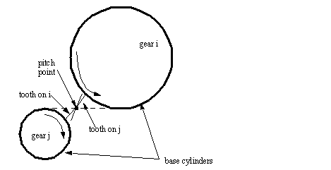
• To construct an involute profile, we need to construct a line that is tangential to both gears. The teeth on both gear will be constructed to contact only on this line.
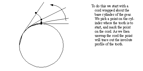
• The involute profiles for a single tooth will trace out a line as shown below (later we will develop an equation for the point on the unwrapping string).
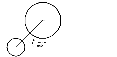
• The pressure angle is shown below,
• Standards geometries for spur gears include, (based on American Gear Manufacturers Association and ANSI standards)
• Typical diametral pitches and modules include, (based on American Gear Manufacturers Association and ANSI standards)
8.3.2 Involute Profiles
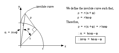
• The figure below shows the triangulated layout for the basic involute function,
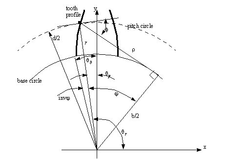
• Next the involute curve is applied to the generation of gear teeth.
• To generate points on these curves we must select values of XXXX and calculate (x, y) positions. These will be correct for one face of the tooth. If these are used to generate a splined curve, or graphed, they will form the tooth profile. The upper and lower bounds are determined by the addendum and dedendum.
8.3.3 Design of Gears
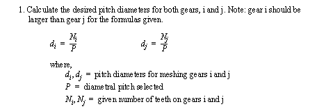
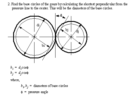
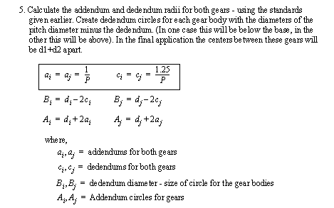
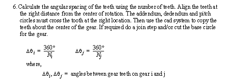
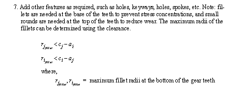
• The basic steps to design a gear are outlines below,
• If we are dealing with a rack, it is effectively a circular gear with an infinite radius.
• When we have internal gears (one gear inside another) we need to adjust the methods to reflect that both gears are on the same side of the pitch line.
8.3.4 Design Issues
• During motion the gear teeth undergo a combination of sliding and rolling. The direction of sliding reverses at the pitch point, where the motion is pure rolling.
8.3.4.1 - Undercutting and Contact Ratios
• Undercutting occurs on some gears. This is a gouging of teeth that occurs when teeth contact below the base circle of the gear during motion.
• During manufacturing some processes (generation) can remove the excess material that lead to undercutting. But this can reduce the base width of the teeth and weakening of the gear.
• Undercutting problems can be reduced by increasing the radius of the gear, and increasing the number of teeth.
• The gear teeth are in contact along the pressure line between the points where it intersects the addendum lines.
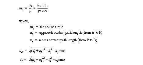
• The contact ratio is as defined below. A value of 1 means that at any time only one tooth is engaged. A value greater than 1 means that only one tooth is engaged. A value of 2 would mean that at any time 2 teeth are engage. A value less than 1 means that at times the teeth are not in contact (bad).
• Undercutting will not occur during production of the profiles if the following addendum values observed,
8.3.4.2 - Changing the Center Distance
• If the center distance between gears is changed, then the pitch circles on both gears will move away from the center.
• The result of the enlarging of pitch circles will be a reduction in the contact ratio. This will lead to a smaller contact ratio.
• This condition also allows some play in the gears (backlash). This play means that a reversing of direction can lead to a small reversing rotation before the other tooth is impacted. This leads to errors and the impact forces can shorten the life of gears significantly.
8.3.5 Helical Gears
• Helical gears are essentially spur gears, but with a bit of a twist in the normally straight profile of the teeth.
egr352a1.jpg
• The helical arrangement means that the teeth engage at one point (as opposed to a line of contact), and then slowly mesh along the face of the tooth. This also means that the number of engaged teeth (contact ratio) can be higher.
• If we contrast spur and helical gears. The spur gear teeth contact fully all at once.
• These gears mesh very smoothly, so they find application for,
- high speeds
- heavy loads
- gear noise must be reduced
- center lines of shafts do not intersect
• These gears,
- require more effort during fabrication
- need additional bearings to resist axial thrust.
• helical gears can be used to transmit torques between parallel, and non-parallel (often perpendicular) shafts.
• To eliminate the need for an axial thrust bearing we can use a herringbone (double helical) gear. This is effectively two helical gears with opposite twists on the helix, and joined down a center line.

8.3.5.1 - Design of Helical Gears
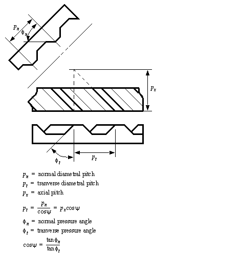
• We can describe the helix with a single angle,
• This helix allows three different ways to measure the pitch and pressure angles.
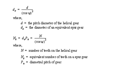
• We can now develop an equivalent pitch radius,
• Typical design parameters include,
- produced for specialized applications, and custom designed
- typical pressure angle is 20°
- for helix angles from 0 to 30° use the normal diametral pitch to calculate tooth proportions
- helix angles greater than 45° are not recommended
- in mating parallel gears - one must have a left hand helix, and the other must have a right hand helix. Use the sign of the helix angle to indicate left or right handed.
• The line of contact in spur gears is straight across the teeth. In helical gears, the line of contact is diagonal.
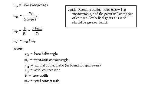
• To measure the contact ratio we need to use three values to be effective,
8.3.5.2 - Perpendicular Helical Gears
• If two shafts intersect at an angle (typically 90°) we can link them using helical gears. The angle between the shafts can be,
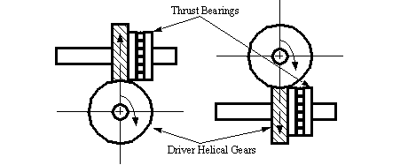
• The example below shows one configuration for helical gears, including the location of thrust bearings.
• When the shaft intersection angle is large (90°) you may use same handed gears to intersect. In the example above the gears are both right handed.
• The pitch diameter for these gears can be found using,
• A minimum contact ratio of 2 is recommended for these gears.
• Typical parameters for cross-axis helical gears are given below,
8.3.6 Bevel Gears
• These gears are like normal spur gears, except that they have a conical form.
egr352a2.jpg
• Their applications are characterized by,
- to couple shafts with intersecting axes
-
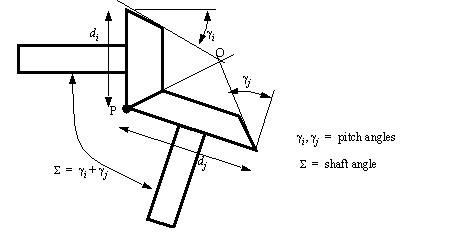
• Bevel gears are meshed so that the points of their cones are coincident.
• As we move towards the point of the cones, the number of teeth remains the same, but the diameter reduces towards zero. This changes the size of the teeth, and the pitch diameter.
• The form of the gears is like that of spur gears, but each has a cone angle, and when added together this gives the angle between the shafts.
• We can apply some of the basic ratios to bevel gears,
8.3.6.1 - Design of Bevel Gears
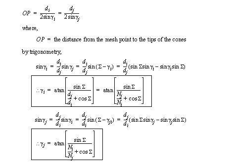
• To determine the pitch angles for the gears we can write the following expressions,
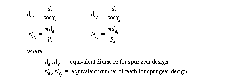
• An approximate methods for creating bevel gears is called ‘Tredgold’s approximation’
• Tredgold’s technique requires that a cone on the bottom of the bear be found. This cone is then flattened out, and normal gear design is done. Finally the cone is mapped back onto the bottom of the gear. The profiles are then projected up to the point of the cone.
• Typical design parameters include,
- 20° pressure angle for straight bevel gears
- bevel gears are always custom made, and are not interchanged
- deflections mean that the wider base tends to take most of the load, so the teeth are designed with a short length (commonly less tan 1/3 of the total cone length)
-
8.3.7 Other Bevelled Gears
• Crown and Face Gear - this gear is much like a rack for spur gears. To get this, one of the gears is given a pitch angle of 90°.
• Spiral Bevel Gears - to reduce noise in beveled gears, a spiral can be added to the teeth.
• Hypoid gears - the centers of the bevelled gears are not coincident - the shaft is offset.
8.3.8 Worm Gears
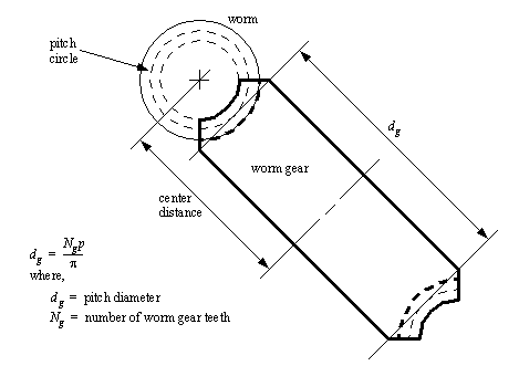
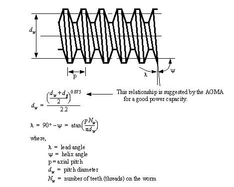
• Worm gears use a long helical screw that drives a larger helical gear.
egr352a3.jpg
• Basically we use a screw like gear (the worm) and a large cylindrical gear (worm gear) that is driven by the worm.
• The worm gear curves to the shape of the worm to increase contact. Also note that worm gear is a helical gear.
• The worm acts very much like a rack, except that it is threaded onto a cylindrical surface.
• These gears find their best applications when a large gear ratio is needed in a compact space. The shafts typically intersect at a 90° angle - when this is the case the helix angle on both gears is the same.
• The worm gear can be single enveloping or double enveloping.
- The single envelope is the parallel sided gear. This type of gear is more forgiving for position and alignment tolerance problems.
- The double enveloping gear has a curvature that increases the surface on contact between the gears. This can be very useful for power applications.
• The following values are reasonable for finding the profile dimensions of the teeth,
• Suggested pressure angles for given lead angles are listed below,
8.3.9 Harmonic Drives
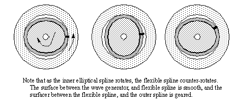
• These are actually normal servo motors, but with an integrated harmonic gear. The harmonic gears are very compact, and as a result the overall size is reduced. These gears also allow very high gear ratios (eg, 100:1)
• Harmonic drives are also gaining popularity with smaller manipulators. They use a rotating elliptical core that deforms a flexible section. The flexible section is in contact with an outer section for short periods of time, and as the ellipse rotates, there is a geared down rotation generated. This allows integral gears in motors
8.3.10 Design With Gears
• When we design gears, cams and mechanisms we are free to set and vary parameters. But, above this we often must select these components to start with.
• The selection of components can be aided by using techniques such as,
- schematics
- ratios
- common approaches
8.3.10.1 - Gear Trains
• When we want to increase/reduce angular displacements/velocities/etc. we can use simple gear trains.
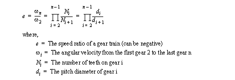
• As we have seen before, gears typically have an input to output ratio. The relationship below is for simple gear trains - only one gear on each axis.
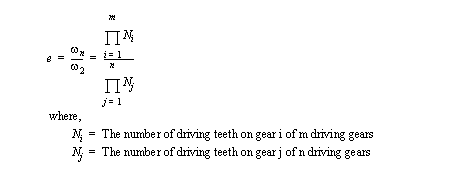
• We can deal with compound gear trains (multiple gears on each axis) by using product of driven and driving teeth.
8.3.10.2 - Examples - Fixed Axis Gears
• A simple gear train has only one gear on each axis.
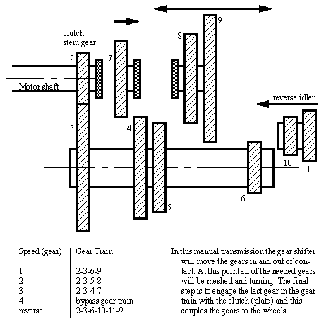
• A compound gear train has multiple gears on the same axis. Consider the truck transmission example from Shigley and Uicker,
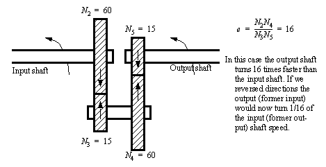
• We may also consider an in-line gear train. These can be used for items such divide by twelve and sixty in clocks,
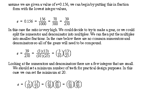
• Quite often we will have a particular speed ratio in mind. We can convert this to teeth numbers by finding a suitable fractional value,
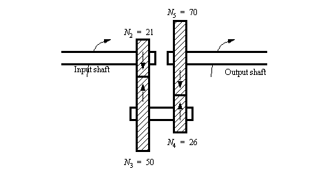
• The gear train in the previous example might look something like,
• Try the design below,
8.3.10.3 - Examples - Moving Axis Gears
• In some cases gears move relative to each other. This can be used to generate some interesting alternatives.
8.3.10.4 - Epicyclic Gear Trains
• Epicyclic gears have many applications, such as automatic transmissions in automobiles.
• In these trains the gears typically orbit each other.
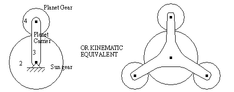
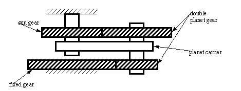
• Consider the basic epicyclic gear train,
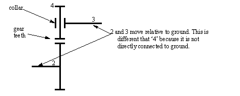
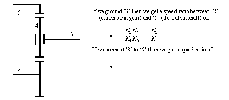
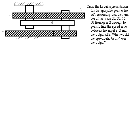
• We can represent these gears using a notation developed by Levai. Consider the basic epicyclic gear,
• When designing with these gears, we can consider different control modes possible. In the case above we could connect the gear ‘4’ to a ring gear (internal gear) and make a simple multispeed transmission.
• Some of the other possible gear train types include variations on the number of planets.
• Consider the compact planetary gear shown below,
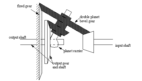
• We can also construct an epicyclic gear using bevel gears. This is called Humpage’s reduction gear.
• Consider the example below,
8.3.10.5 - Differentials
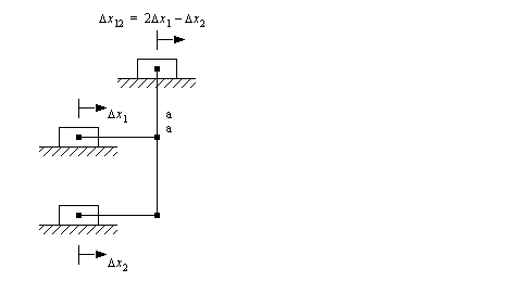
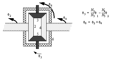
• Differential mechanisms allow us to effectively do subtraction or averaging.
• If we want to determine the difference between two linear motions we could a mechanism like the one shown below,
• An angular differential is shown below using bevel gears,
************** include image here
• In one type of automotive differential the housing above is driven, and both the output shafts turn. This allows a small difference in wheel speed. Without this simple action like turning corners would exert large forces on the tires and drive train. This is also why one of the drive wheels can spin while the other is fixed.
• Various vehicles can disengage the differential for offroad conditions (where tires can slip), while others have mechanisms to balance torque to the wheels when an excessive difference in speed is detected.
• Worm gears have also been used in automotive differentials.
8.3.11 Gear Forces and Torques
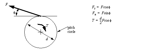
• The involute profile of the gear means that the force applied at the gear teeth is not tangent to the pitch line, but actually tangent to the base circle. At the pitch point the force between the teeth acts at the pressure angle.
• For spur gears the following values and equations can be used for the applied forces. Clearly there would be a reaction force that is not shown here. (Note: this applies even if multiple teeth are in contact).
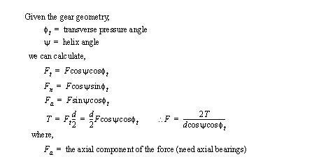
• If we are considering helical gears the helical spiral of the teeth adds a second angle to the contact force. This means that the contact force requires 3D analysis.
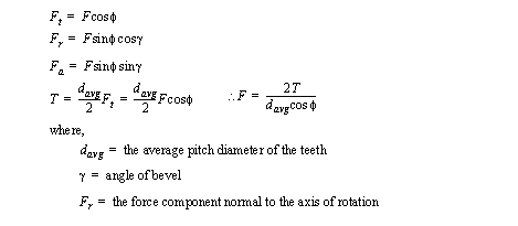
• Straight bevel gears are not so easy to calculate because the force is applied at a variable distance from the center of the rotational axis.
• In these gears we compromise by assuming the force is applied at the center of the tooth. In actuality this force will be further from the center of the gear.
• We can calculate force components using the relationships below,
• For all of these gears we need to use the calculated forces to design bearings and supports. Most notably the axial thrusts require thrust bearings be included in the design.
