LOGIC DESIGNDesign ideas can be converted to Boolean equations directly, or with other techniques discussed later. The Boolean equation form can then be simplified or rearranges, and then converted into ladder logic, or a circuit. 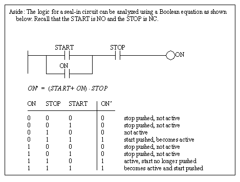
If we can describe how a controller should work in words, we can often convert it directly to a Boolean equation, as shown in Figure 5.1 Boolean Algebra Based Design of Ladder Logic. In the example a process description is given first. In actual applications this is obtained by talking to the designer of the mechanical part of the system. In many cases the system does not exist yet, making this a challenging task. The next step is to determine how the controller should work. In this case it is written out in a sentence first, and then converted to a Boolean expression. The Boolean expression may then be converted to a desired form. The first equation contains an EOR, which is not available in ladder logic, so the next line converts this to an equivalent expression (2) using ANDs, ORs and NOTs. The ladder logic developed is for the second equation. In the conversion the terms that are ANDed are in series. The terms that are ORed are in parallel branches, and terms that are NOTed use normally closed contacts. The last equation (3) is fully expanded and ladder logic for it is shown in Figure 5.1 Alternate Ladder Logic. This illustrates the same logical control function can be achieved with different, yet equivalent, ladder logic. 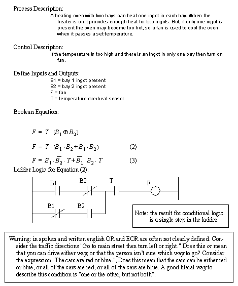
Figure 5.1 Boolean Algebra Based Design of Ladder Logic 
Figure 5.1 Alternate Ladder Logic Boolean algebra is often used in the design of digital circuits. Consider the example in Figure 5.1 Reverse Engineering of a Digital Circuit. In this case we are presented with a circuit that is built with inverters, nand, nor and, and gates. This figure can be converted into a boolean equation by starting at the left hand side and working right. Gates on the left hand side are solved first, so they are put inside parentheses to indicate priority. Inverters are represented by putting a NOT operator on a variable in the equation. This circuit can’t be directly converted to ladder logic because there are no equivalents to NAND and NOR gates. After the circuit is converted to a Boolean equation it is simplified, and then converted back into a (much simpler) circuit diagram and ladder logic. 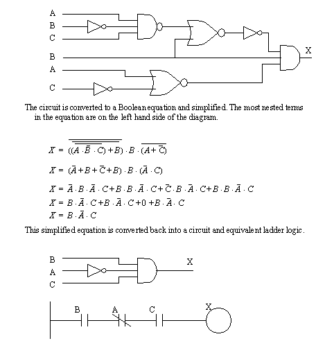
Figure 5.1 Reverse Engineering of a Digital Circuit To summarize, we will obtain Boolean equations from a verbal description or existing circuit or ladder diagram. The equation can be manipulated using the axioms of Boolean algebra. after simplification the equation can be converted back into ladder logic or a circuit diagram. Ladder logic (and circuits) can behave the same even though they are in different forms. When simplifying Boolean equations that are to be implemented in ladder logic there are a few basic rules. 1. Eliminate NOTs that are for more than one variable. This normally includes replacing NAND and NOR functions with simpler ones using DeMorgan’s theorem. 2. Eliminate complex functions such as EORs with their equivalent. These principles are reinforced with another design that begins in Figure 5.1 A Boolean Equation and Derived Circuit and Ladder Logic. Assume that the Boolean equation that describes the controller is already known. This equation can be converted into both a circuit diagram and ladder logic. The circuit diagram contains about two dollars worth of integrated circuits. If the design was mass produced the final cost for the entire controller would be under $50. The prototype of the controller would cost thousands of dollars. If implemented in ladder logic the cost for each controller would be approximately $500. Therefore a large number of circuit based controllers need to be produced before the break even occurs. This number is normally in the range of hundreds of units. There are some particular advantages of a PLC over digital circuits for the factory and some other applications. • the PLC will be more rugged, • the program can be changed easily • less skill is needed to maintain the equipment 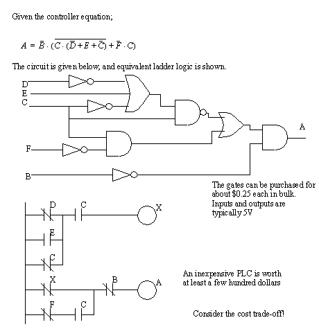
Figure 5.1 A Boolean Equation and Derived Circuit and Ladder Logic The initial equation is not the simplest. It is possible to simplify the equation to the form seen in Figure 5.1 A Boolean Equation and Derived Circuit and Ladder Logic. If you are a visual learner you may want to notice that some simplifications are obvious with ladder logic - consider the C on both branches of the ladder logic in Figure 5.1 The Simplified Form of the Example. 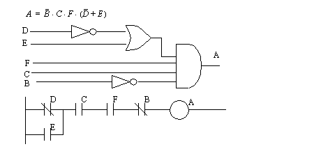
Figure 5.1 The Simplified Form of the Example The equation can also be manipulated to other forms that are more routine but less efficient as shown in Figure 5.1 A Canonical Logic Form. The equation shown is in disjunctive normal form - in simpler words this is ANDed terms ORed together. This is also an example of a canonical form - in simpler terms this means a standard form. This form is more important for digital logic, but it can also make some PLC programming issues easier. For example, when an equation is simplified, it may not look like the original design intention, and therefore becomes harder to rework without starting from the beginning. 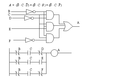
Figure 5.1 A Canonical Logic Form 5.1.1 Boolean Algebra TechniquesThere are some common Boolean algebra techniques that are used when simplifying equations. Recognizing these forms are important to simplifying Boolean Algebra with ease. These are itemized, with proofs in Figure 5.1 Common Boolean Algebra Techniques. 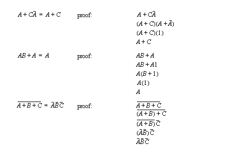
|