31. SELECTING A PLC• Estimating program memory and time requirements • Be able to select a hardware and software vendor. • Be able to size a PLC to an application • Be able to select needed hardware and software. After the planning phase of the design, the equipment can be ordered. This decision is usually based upon the required inputs, outputs and functions of the controller. The first decision is the type of controller; rack, mini, micro, or software based. This decision will depend upon the basic criteria listed below. • Number of logical inputs and outputs. • Memory - Often 1K and up. Need is dictated by size of ladder logic program. A ladder element will take only a few bytes, and will be specified in manufacturers documentation. • Number of special I/O modules - When doing some exotic applications, a large number of special add-on cards may be required. • Scan Time - Big programs or faster processes will require shorter scan times. And, the shorter the scan time, the higher the cost. Typical values for this are 1 microsecond per simple ladder instruction • Communications - Serial and networked connections allow the PLC to be programmed and talk to other PLCs. The needs are determined by the application. • Software - Availability of programming software and other tools determines the programming and debugging ease. The process of selecting a PLC can be broken into the steps listed below. 1. Understand the process to be controlled (Note: This is done using the design sheets in the previous chapter). • List the number and types of inputs and outputs. • Determine how the process is to be controlled. • Determine special needs such as distance between parts of the process. 2. If not already specified, a single vendor should be selected. Factors that might be considered are, (Note: Vendor research may be needed here.) • Support while developing programs • The range of products available • Support while troubleshooting • Shipping times for emergency replacements • The track record for the company • Business practices (billing, upgrades/obsolete products, etc.) 3. Plan the ladder logic for the controls. (Note: Use the standard design sheets.) 4. Count the program instructions and enter the values into the sheets in Figure 31.1 Memory and Time Tally Sheet and Figure 31.1 Memory and Timer Requirement Sheet. Use the instruction times and memory requirements for each instruction to determine if the PLC has sufficient memory, and if the response time will be adequate for the process. Samples of scan times and memory are given in Figure 31.1 Typical Instruction Times and Memory Usage for a Micrologix Controller and Figure 31.1 Typical Instruction Times and Memory Usage for a PLC-5 Controller. 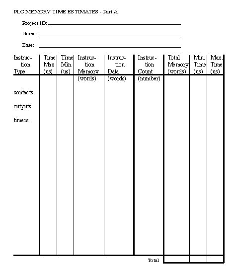
Figure 31.1 Memory and Time Tally Sheet 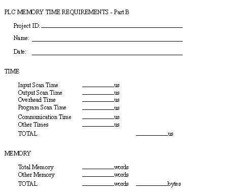
Figure 31.1 Memory and Timer Requirement Sheet 5. Look for special program needs and check the PLC model. (e.g. PID) 6. Estimate the cost for suitable hardware, programming software, cables, manuals, training, etc., or ask for a quote from a vendor. 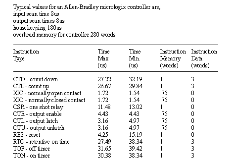
Figure 31.1 Typical Instruction Times and Memory Usage for a Micrologix Controller 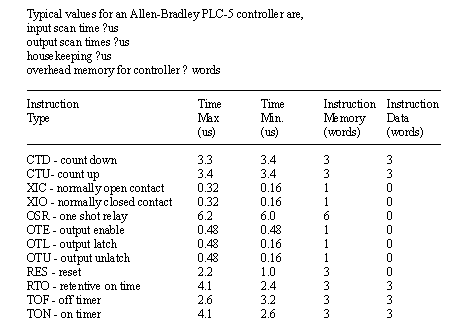
Figure 31.1 Typical Instruction Times and Memory Usage for a PLC-5 Controller |