BLOCK LOGICThe first step is to name each block in the flowchart, as shown in Figure 10.1 Labeling Blocks in the Flowchart. Each of the numbered steps will then be converted to ladder logic 
Figure 10.1 Labeling Blocks in the Flowchart Each block in the flowchart will be converted to a block of ladder logic. To do this we will use the MCR (Master Control Relay) instruction (it will be discussed in more detail later.) The instruction is shown in Figure 10.1 The MCR Function, and will appear as a matched pair of outputs labelled MCR. If the first MCR line is true then the ladder logic on the following lines will be scanned as normal to the second MCR. If the first line is false the lines to the next MCR block will all be forced off. If a normal output is used inside an MCR block, it may be forced off. Therefore latches will be used in this method. 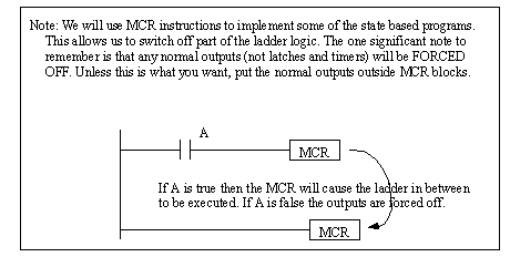
The first part of the ladder logic required will reset the logic to an initial condition, as shown in Figure 10.1 Initial Reset of States. The line will only be true for the first scan of the PLC, and at that time it will turn on the flowchart block F1 which is the reset all values off operation. All other operations will be turned off. 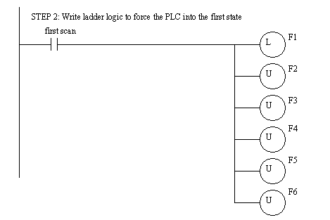
Figure 10.1 Initial Reset of States The ladder logic for the first state is shown in Figure 10.1 Ladder Logic for the Operation F1. When F1 is true the logic between the MCR lines will be scanned, if F1 is false the logic will be ignored. This logic turns on the outlet valve and turns off the inlet valve. It then turns off operation F1, and turns on the next operation F2. 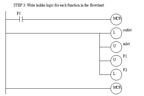
Figure 10.1 Ladder Logic for the Operation F1 The ladder logic for operation F2 is simple, and when the start button is pushed, it will turn off F2 and turn on F3. The ladder logic for operation F3 opens the inlet valve and moves to operation F4. 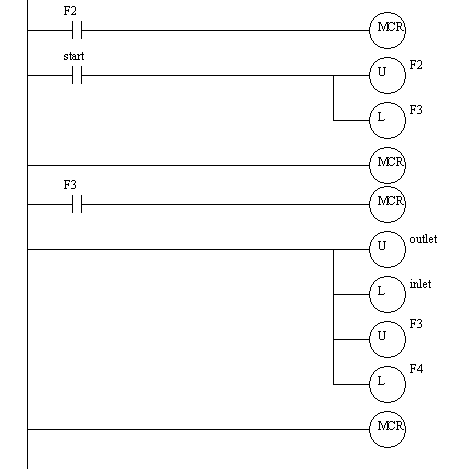
Figure 10.1 Ladder Logic for Flowchart Operations F2 and F3 The ladder logic for operation F4 turns off F4, and if the tank is full it turns on F6, otherwise F5 is turned on. The ladder logic for operation F5 is very similar. 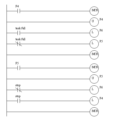
Figure 10.1 Ladder Logic for Operations F4 and F5 The ladder logic for operation F6 turns the outlet valve on and turns off the inlet valve. It then ends operation F6 and returns to operation F2. 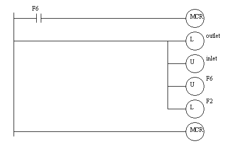
|